Mastering Serial Communication in Embedded C
Category: Embedded Systems
Unlock the Power of Serial Communication in Embedded C
If you're a tech enthusiast, hobbyist, or developer working with Raspberry Pi or microcontroller projects, you know efficient communication between devices is crucial. Serial communication stands out as a fundamental skill in embedded C programming, enabling your projects to send and receive data reliably across UART, SPI, and I2C interfaces. But mastering serial communication can be challenging: dealing with hardware registers, managing buffers, ensuring error-free data transmission, and optimizing performance often become stumbling blocks even for experienced developers.
You've landed on this post looking for a clear, concise, and practical guide that cuts through complex jargon and gets straight to what you need — understanding serial ports programming using embedded C to level up your projects. Unlike generic or overly theoretical tutorials, this article dives deep into real-world applications, step-by-step code explanations, and best practices tailored for embedded systems development.
Whether you're building a sensor network, a custom peripheral controller, or integrating your Raspberry Pi with microcontrollers, this post will equip you with the knowledge and tools to harness serial communication effectively. Read on to decode registers, set baud rates, handle interrupts, and troubleshoot communications seamlessly—getting your embedded applications talking like pros.
- Unlock the Power of Serial Communication in Embedded C
- Overview of Serial Communication Protocols in Embedded Systems: UART, SPI, and I2C — Definitions and Use Cases
- Setting Up Serial Communication in Embedded C: Configuring Baud Rate, Data Bits, Stop Bits, and Parity
- Interfacing with Hardware Registers: Understanding Microcontroller UART Registers and Their Role in Data Transmission
- Writing Efficient Embedded C Code for Serial Communication: Polling vs Interrupt-driven Mechanisms
- Implementing Error Detection and Handling: Parity Errors, Framing Errors, and Buffer Overflows
- Using Circular Buffers for Serial Data Management to Improve Performance and Reliability
- Debugging Serial Communication Issues: Tools, Techniques, and Common Problems in Embedded C
- Integrating Serial Communication with Raspberry Pi and Peripheral Microcontrollers: Practical Examples
- Advanced Topics: DMA (Direct Memory Access) in Serial Communication for High-Speed Data Transfer
- Best Practices and Optimization Tips for Robust and Power-Efficient Serial Communication in Embedded Systems
- Optimize Baud Rate and Frame Settings for Stability and Speed
- Employ Interrupt-Driven Communication with Circular Buffers
- Minimize Power Consumption by Selective Peripheral and CPU Usage
- Implement Comprehensive Error Detection and Recovery Mechanisms
- Keep Code Modular and Hardware Abstraction Consistent
Overview of Serial Communication Protocols in Embedded Systems: UART, SPI, and I2C — Definitions and Use Cases
Serial communication protocols form the backbone of embedded systems, enabling efficient data exchange between microcontrollers, sensors, actuators, and other peripherals. The three most widely used protocols—UART (Universal Asynchronous Receiver/Transmitter), SPI (Serial Peripheral Interface), and I2C (Inter-Integrated Circuit)—each bring unique characteristics and advantages tailored to specific application needs. Understanding their fundamental differences, operational principles, and best-fit use cases is essential for selecting the right communication method in your embedded C projects.
-
UART is a straightforward, asynchronous serial protocol commonly used for point-to-point communication. It requires only two wires (TX and RX) and relies on pre-agreed baud rates for timing, making it ideal for long-distance, low-speed data transfer like debugging, GPS modules, and serial console interfaces.
-
SPI is a high-speed, synchronous protocol designed for short-distance communication between a master device and multiple slaves. With separate lines for clock (SCLK), master output/slave input (MOSI), master input/slave output (MISO), and chip-select (CS), SPI excels in applications demanding fast data rates and full-duplex communication—such as memory cards, LCD displays, and high-speed sensors.
-
I2C offers a compact, multi-master, multi-slave synchronous interface using just two bidirectional lines: Serial Data (SDA) and Serial Clock (SCL). Its built-in addressing and collision detection make it perfect for connecting various low-speed peripherals like EEPROMs, temperature sensors, and real-time clocks, especially where pin count and wiring complexity need to be minimized.
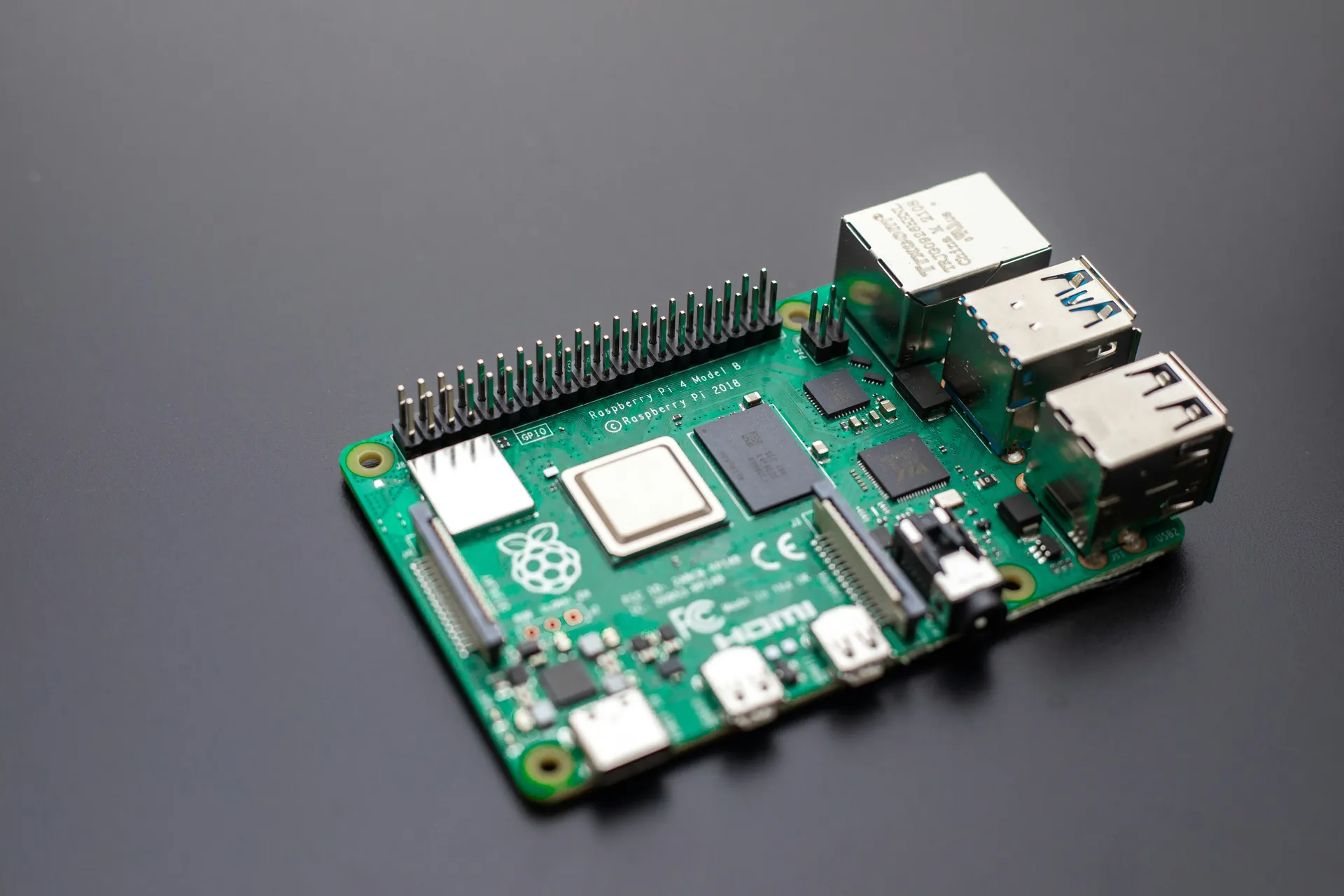
By mastering these protocols in embedded C, you unlock the power to design versatile, scalable, and efficient communication architectures tailored for your Raspberry Pi and microcontroller projects—whether it’s streaming sensor data, controlling displays, or coordinating complex peripheral networks.
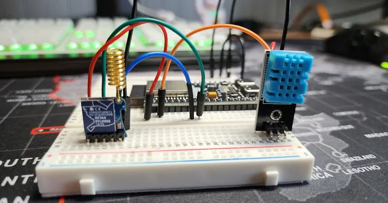
Image courtesy of Bmonster Lab
Setting Up Serial Communication in Embedded C: Configuring Baud Rate, Data Bits, Stop Bits, and Parity
To establish reliable serial communication in embedded C, correctly configuring the UART peripheral parameters is crucial. These parameters—baud rate, data bits, stop bits, and parity—define how data frames are structured and transmitted, directly impacting data integrity and synchronization between devices.
Configuring Baud Rate
The baud rate sets the speed of data transmission, measured in bits per second (bps). Both transmitting and receiving devices must agree on the same baud rate to avoid framing errors and data loss. In embedded C, configuring baud rate typically involves calculating a value to load into a UART baud rate register based on the system clock frequency. For example, the formula often looks like this:
UBRR_Value = (F_CPU / (16UL * BaudRate)) - 1;
Where F_CPU is the CPU clock frequency and BaudRate is the desired communication speed (e.g., 9600, 115200 bps). Setting this correctly ensures the UART module samples data bits accurately.
Setting Data Bits, Stop Bits, and Parity
The data frame format defines how many bits make up a character and how the line signals the end of that character. The common UART configurations include:
- Data bits: Typically 5 to 8 bits per character; 8 bits is standard in most embedded applications.
- Stop bits: Indicate the end of a data frame; usually 1 or 2 bits.
- Parity: Provides a simple error detection mechanism with options such as none, even, or odd parity.
Correctly configuring these parameters involves setting control registers, often named UCSRC, UART_CTRL, or similar, depending on your microcontroller architecture. For example, you might use embedded C bitwise operations to enable odd parity and two stop bits like this:
UCSRC = (1 << URSEL) | (1 << USBS) | (1 << UPM1) | (0 << UPM0); // 2 Stop bits, Odd Parity
Why These Settings Matter
Incorrect baud rate or frame format causes framing errors, data corruption, or complete communication failure. Matching these settings on both ends guarantees that data packets are interpreted correctly, minimizing retransmissions and maximizing efficiency. When designing your embedded applications—whether connecting sensors, GPS modules, or communicating with your Raspberry Pi—taking the time to configure serial communication parameters precisely is foundational to robust system performance.
By mastering these configurations in embedded C, you not only ensure stable UART communication but also gain flexibility to tailor serial interfaces for diverse project requirements and hardware constraints.
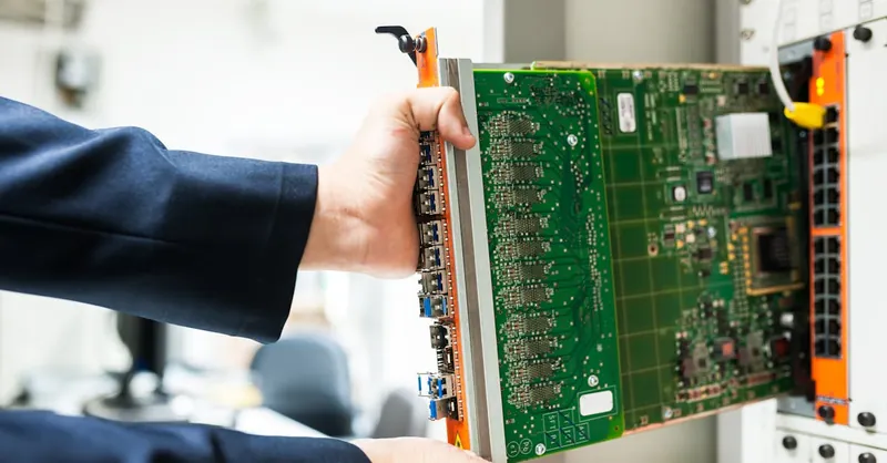
Image courtesy of panumas nikhomkhai
Interfacing with Hardware Registers: Understanding Microcontroller UART Registers and Their Role in Data Transmission
At the heart of serial communication in embedded C lies direct interaction with microcontroller UART hardware registers. These registers control and monitor every aspect of the UART peripheral—from setting baud rates and frame formats to handling data transmission and reception. Grasping the function and configuration of these registers is essential to unlock precise, low-level control for your embedded projects.
Key UART Registers and Their Functions
-
Baud Rate Registers (e.g., UBRR, BRR)
These registers set the timing for data bits over the serial line. By programming the baud rate registers based on your system clock, you ensure the UART transmits and receives bits at a consistent, agreed-upon speed, reducing framing errors and timing mismatches. -
Control Registers (e.g., UCSRA, UCSRB, UART_CTRL)
Control registers enable or disable the UART transmitter and receiver, configure frame formats (data bits, stop bits, parity), and manage interrupt enables for transmit/receive events or errors. Bitwise manipulation of control register flags is central to activating the desired UART features without affecting others. -
Status Registers (e.g., UCSRA, UART_STAT)
These provide real-time feedback on transmission status, buffer readiness, error detection (parity error, frame error, overrun), and interrupt flags. Polling or interrupt-driven approaches typically check these registers to determine when to read or write data. -
Data Registers (e.g., UDR, UART_DATA)
The data register holds the next byte to be transmitted or the most recently received byte. Writing to this register starts transmission; reading from it retrieves incoming data. Proper synchronization with status flags ensures no loss or overwriting of data.
Why Understanding UART Registers Maximizes Reliability and Performance
Mastering UART registers allows you to:
- Customize functionality for specific application needs, such as setting non-standard baud rates or enabling multi-processor communication modes.
- Implement efficient interrupt-driven communication by configuring interrupt enable bits and handling respective flags, leading to more responsive and CPU-efficient designs.
- Detect and handle transmission errors proactively by monitoring status flags, improving robustness in noisy or complex environments.
- Optimize power consumption by selectively enabling transmitter or receiver components only when needed through control register bits.
Without a thorough understanding of these registers and their interdependencies, developers may face intermittent errors, unpredictable behavior, or suboptimal performance in embedded serial communication.
In embedded C programming for microcontrollers and Raspberry Pi peripherals, direct register manipulation remains the most powerful way to seize full control of UART communication, surpassing generic driver APIs in flexibility and efficiency. As you delve deeper into embedded serial communication, a strong command of UART registers will empower you to build resilient, high-performance data transmission links tailored precisely to your project needs.
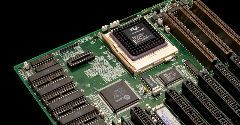
Image courtesy of Nicolas Foster
Writing Efficient Embedded C Code for Serial Communication: Polling vs Interrupt-driven Mechanisms
When implementing serial communication in embedded C, choosing between polling and interrupt-driven methods is crucial for optimizing performance, CPU utilization, and responsiveness in your Raspberry Pi and microcontroller projects. Both approaches handle data transmission and reception but differ significantly in how they interact with the CPU and peripheral hardware.
Polling: Simplicity at the Cost of Efficiency
Polling involves the CPU actively and repeatedly checking status flags in UART registers (such as the Data Register Empty or Receive Complete flags) to determine when to send or read data. It is straightforward to implement and suitable for simple, low-speed applications or during system initialization. However, polling can lead to CPU blocking because the processor wastes valuable cycles waiting for communication events instead of performing other tasks.
Advantages of Polling: - Easy to implement in beginner-level projects. - No complex interrupt handling or context switching. - Suitable for minimal data rates or single-threaded systems.
Disadvantages of Polling: - Inefficient CPU usage; wastes cycles on busy-wait loops. - Poor scalability for multitasking or real-time applications. - Risk of missed data if polling intervals are too long.
Interrupt-driven Mechanisms: Efficient and Responsive Communication
Interrupt-driven serial communication leverages the microcontroller’s hardware interrupt system to notify the CPU as soon as a data event occurs (such as receiving a byte or buffer readiness). Upon interrupt, the CPU pauses its current task, executes an Interrupt Service Routine (ISR) to handle the serial data, then resumes its previous process. This approach drastically improves CPU efficiency and responsiveness, making it indispensable for high-speed or multitasking embedded systems.
Key Benefits of Interrupt-driven Communication: - Enables non-blocking serial data transfer allowing concurrent processing. - Immediate reaction to data reception/transmission events. - Minimizes latency and prevents buffer overruns or data loss. - Facilitates scalable designs suitable for complex Raspberry Pi and microcontroller projects.
Balancing Between Both Approaches
In practice, many embedded systems adopt a hybrid model—using interrupts to handle incoming data efficiently while employing polling for less time-critical transmission. This hybrid strategy balances the complexity of interrupt management with polling’s simplicity, optimizing overall system performance.
When designing embedded C code for serial communication, consider these factors:
- System Complexity: Interrupts are preferable for multitasking or real-time applications.
- Data Rate and Throughput: High-speed serial interfaces benefit from interrupts to avoid dropped data.
- CPU Load and Power Consumption: Interrupts reduce unnecessary CPU activity, improving energy efficiency.
- Development Time and Debugging: Polling is simpler to debug, but interrupts offer long-term robustness.
Optimizing your serial communication code by choosing between polling and interrupt-driven mechanisms is a fundamental step to ensure reliable, low-latency, and resource-efficient data exchange in embedded systems development. Mastering these methods enhances your ability to build responsive, power-conscious microcontroller and Raspberry Pi projects with clean, maintainable embedded C code.
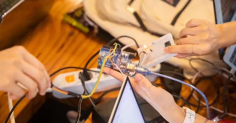
Image courtesy of Youn Seung Jin
Implementing Error Detection and Handling: Parity Errors, Framing Errors, and Buffer Overflows
In embedded serial communication, error detection and handling are critical to maintaining data integrity and ensuring reliable interaction between microcontrollers, Raspberry Pi, and peripheral devices. Common issues such as parity errors, framing errors, and buffer overflows can corrupt data transmission or cause loss of information, ultimately degrading system performance. By implementing robust error detection and management strategies in embedded C, you can safeguard your projects against these pitfalls and build dependable communication links.
Parity Errors: Detecting Single-Bit Data Corruption
Parity is a simple yet effective method for detecting single-bit errors during UART communication. When parity checking is enabled (even, odd, or forced), the transmitting device appends a parity bit calculated based on the data bits’ values. The receiver recalculates parity and compares it to the received parity bit; a mismatch signals a parity error indicating data corruption.
Handling parity errors involves:
- Monitoring UART status registers for parity error flags.
- Discarding or requesting retransmission of affected data packets.
- Optionally implementing higher-layer protocols in your communication stack to correct or log errors.
Though parity cannot correct errors, it acts as a first line of defense against noise-induced bit flips in noisy environments, making it indispensable for mission-critical serial links.
Framing Errors: Recognizing Incorrect Frame Boundaries
Framing errors occur when the receiver fails to detect the correct stop bit, implying that byte boundaries were misinterpreted. This usually results from baud rate mismatches, signal noise, or timing inaccuracies. A framing error can cause the receiver to misalign subsequent bits, effectively corrupting the entire data stream.
To manage framing errors:
- Confirm baud rate and frame format consistency on both transmitter and receiver sides.
- Check the framing error bit in UART status registers after each received byte.
- Implement logic to resynchronize the receiver or flush buffers upon error detection to maintain data alignment.
Robust framing error handling improves the resilience of serial communication, especially in environments prone to electrical interference or when interfacing with diverse hardware.
Buffer Overflows: Preventing Data Loss During High Throughput
The UART hardware and software buffers temporarily store incoming and outgoing data. A buffer overflow happens when data arrives faster than it is processed, causing new bytes to overwrite unread data, leading to permanent loss.
Effective buffer overflow management includes:
- Implementing interrupt-driven data handling to read and write data promptly.
- Using adequately sized circular buffers and carefully managing buffer pointers.
- Monitoring overrun error flags in status registers to detect overflow conditions.
- Applying flow control mechanisms such as hardware RTS/CTS or software XON/XOFF to prevent overwhelming the receiver.
Properly handling buffer overflows ensures your embedded systems maintain smooth data flow, even under heavy communication loads or multitasking conditions.
By integrating comprehensive error detection and handling techniques for parity errors, framing errors, and buffer overflows into your embedded C serial communication code, you achieve robust, fault-tolerant communication. This foundation is crucial for complex Raspberry Pi and microcontroller projects, where data accuracy and system stability directly impact real-world functionality.

Image courtesy of Polina Zimmerman
Using Circular Buffers for Serial Data Management to Improve Performance and Reliability
Efficient serial data management is pivotal in embedded C applications, especially when dealing with high-speed UART communication or multitasking environments on Raspberry Pi and microcontrollers. One of the most effective techniques to enhance both performance and reliability is the implementation of circular buffers (also known as ring buffers). Circular buffers provide a continuous, FIFO (First-In, First-Out) data structure that elegantly handles asynchronous data streams without requiring costly memory reallocations or complex queue management.
Why Use Circular Buffers in Serial Communication?
Serial interfaces often receive data at unpredictable intervals, while your embedded system may process incoming bytes at a different pace. Without buffering, this mismatch can lead to data loss, buffer overruns, or extended CPU blocking. Circular buffers solve these challenges by:
- Allowing non-blocking reads and writes, which means incoming serial data can be stored immediately by the interrupt service routine (ISR) without waiting for the main application to process it.
- Providing a fixed-size buffer that automatically wraps around, efficiently utilizing memory with minimal overhead.
- Enabling smooth handling of variable data rates without dropping bytes, improving overall system stability.
- Simplifying buffer pointer management through modular arithmetic, reducing code complexity and runtime errors.
Implementing Circular Buffers in Embedded C for UART
A typical circular buffer maintains two pointers or indices:
- Head (write pointer): Marks the position where the next incoming byte will be stored.
- Tail (read pointer): Indicates the position of the next byte to be read by the application.
As bytes arrive from the UART ISR, they are inserted at the head position, which then advances. The application reads bytes from the tail position, also advancing it after consumption. When the head catches up to the tail, the buffer is considered full, prompting either overwriting prevention or data discard logic.
Key steps to implement an efficient circular buffer for serial data:
- Define a buffer array with a power-of-two length (e.g., 128 bytes) to leverage bitwise masking for index wrapping.
- Use volatile qualifiers for buffer pointers when accessed by both ISR and main code to prevent compiler optimization issues.
- Design the UART receive ISR to quickly store incoming bytes into the buffer and update the head pointer.
- Implement a non-blocking function in the main loop to read available bytes from the buffer based on the tail pointer.
- Monitor buffer fullness to prevent overflows, optionally signaling warnings or flow-control triggers.
Benefits for Raspberry Pi and Microcontroller Projects
Integrating circular buffers into your embedded serial communication stack markedly enhances your project's ability to:
- Handle bursty or continuous data streams without missing bytes.
- Reduce CPU overhead by offloading immediate data handling to ISRs while the main application processes data efficiently.
- Maintain consistent data flow even under interrupt-heavy or multitasking conditions common in sophisticated sensor networks or peripheral control systems.
- Boost communication robustness by preventing buffer overrun errors that can otherwise degrade system reliability.
By mastering circular buffer techniques in embedded C, you empower your Raspberry Pi and microcontroller projects with resilient, efficient serial communication capable of meeting demanding real-world data throughput and timing requirements. This foundation is invaluable as your projects grow in complexity and scale.

Image courtesy of Bmonster Lab
Debugging Serial Communication Issues: Tools, Techniques, and Common Problems in Embedded C
Debugging serial communication in embedded C can often be a daunting task due to the low-level nature of the hardware interactions and the asynchronous timing involved. However, a systematic approach combined with the right tools and techniques can dramatically reduce troubleshooting time and improve the reliability of your UART, SPI, or I2C implementations across Raspberry Pi and microcontroller projects.
Common Serial Communication Problems to Watch For
- Baud Rate Mismatch: One of the most frequent issues causing framing errors or garbled data. Always verify that both devices use the exact baud rate, including clock source accuracy and any divider settings.
- Incorrect Frame Configuration: Mismatched data bits, parity, or stop bits settings can lead to continuous errors or lost bytes.
- Buffer Overflows: Occur when incoming data is not read quickly enough, causing loss of bytes and triggering overrun errors.
- Signal Integrity Issues: Noise, ground loops, or improper wiring can corrupt data—often manifesting as sporadic errors difficult to reproduce.
- Incorrect Register Configuration: Improper manipulation of UART control or status registers can disable transmitter/receiver or interrupts unintentionally.
- Interrupt Conflicts: Overlapping ISRs or priority issues can cause missed or delayed data handling, especially in interrupt-driven communication.
Essential Tools for Troubleshooting Serial Communication
- Logic Analyzers: A logic analyzer is indispensable for visualizing serial data streams in real time. It allows you to decode UART, SPI, or I2C signals bit-by-bit, verifying timing, and detecting anomalies like missing stop bits or incorrect clock polarity.
- Serial Terminal Emulators: Tools like PuTTY, Tera Term, or minicom enable easy testing of UART communication via USB-to-serial adapters, allowing quick interaction and verification of data correctness.
- Oscilloscopes: Helpful to probe physical lines for voltage levels and signal noise, crucial when suspecting hardware wiring or power issues.
- On-Chip Debuggers and IDEs: Integrated debugging with breakpoints and register views allow you to monitor UART registers, buffer states, and ISR execution flows directly in embedded C programs.
Proven Techniques to Isolate and Fix Issues
- Validate Configuration First: Double-check baud rate calculations, frame format bits, and enable flags before proceeding to complex debugging.
- Use Loopback Tests: Implement internal or external loopback (connecting TX to RX) to verify the sender and receiver functions independently from the external device.
- Incremental Development: Start with simple communication (e.g., single byte transmit/receive) before implementing complex protocols or buffering.
- Monitor Status Registers: Continuously check UART status flags for error conditions such as parity or framing errors during run-time.
- Isolate Interrupts: Temporarily disable interrupts and test polling-based communication to determine if ISR conflicts are the cause.
- Add Debug Logging: Output diagnostic messages over serial or LEDs to trace code execution paths and data flow without a full debugger.
By mastering these debugging strategies and leveraging specialized hardware and software tools, you can efficiently identify and resolve serial communication problems in embedded C. This ensures your Raspberry Pi and microcontroller projects achieve robust, error-free data exchange critical for complex sensor networks, peripheral interfacing, and real-time embedded applications.

Image courtesy of Mikhail Nilov
Integrating Serial Communication with Raspberry Pi and Peripheral Microcontrollers: Practical Examples
Bridging communication between a Raspberry Pi and peripheral microcontrollers via serial interfaces like UART, SPI, or I2C unlocks a vast realm of creative and functional embedded projects. Whether you’re building sensor hubs, motor controllers, or custom IoT nodes, understanding practical integration techniques ensures smooth data exchange, synchronization, and real-time control across heterogeneous platforms.
Practical UART Integration Between Raspberry Pi and Microcontrollers
UART remains the simplest and most widely used protocol for serial communication between Raspberry Pi and microcontrollers such as Arduino or STM32. To implement this:
- Hardware Connection: Connect the Raspberry Pi’s UART TX pin to the microcontroller RX pin, and vice versa, ensuring common ground reference. Remember to check voltage levels; Raspberry Pi’s GPIO operates at 3.3V while some microcontrollers are 5V tolerant—consider level shifters if necessary.
- Configure Serial Parameters: Match baud rate, data bits, parity, and stop bits exactly on both ends using embedded C on the microcontroller and Linux system settings (
sttyor Python’spyserialon Raspberry Pi). - Embedded C Implementation: Write efficient UART drivers on the microcontroller that handle interrupts and circular buffers for reliable data flow, while the Raspberry Pi can run scripts or applications that open serial ports and process incoming data.
- Example Use Case: Sending sensor readings from a microcontroller to Raspberry Pi for logging or visualization, where the microcontroller streams formatted ASCII or binary data via UART and the Pi parses and stores it.
SPI and I2C: Expanding Raspberry Pi’s Peripheral Ecosystem
While UART is excellent for point-to-point links, SPI and I2C enable Raspberry Pi to act as a master device communicating with multiple microcontroller-based peripherals.
-
SPI Integration:
Configure the Raspberry Pi’s SPI interface (via/dev/spidev*) and embedded C SPI drivers on peripherals to perform fast, full-duplex data transfers. SPI is ideal for high-speed sensors, displays, or memory devices controlled by microcontrollers acting as slaves. -
I2C Integration:
With its multi-master capabilities, I2C allows Raspberry Pi to communicate with several low-speed peripherals on the same bus using unique addresses. On the microcontroller side, embedded C code must implement I2C slave routines to respond to the Pi’s queries or commands.
When integrating via SPI or I2C, pay special attention to bus voltages, pull-up resistor requirements (I2C), and clock stretching. Synchronization and bus arbitration handled in your embedded C routines ensure efficient multi-device communication.
Best Practices for Reliable Cross-Platform Serial Communication
- Consistent Protocol Settings: Maintain exact parity, stop bits, and baud rate configurations on both Raspberry Pi and microcontroller sides.
- Robust Buffer Management: Implement circular buffers and interrupt-driven data handling on microcontrollers to avoid data loss during asynchronous communications.
- Error Handling: Incorporate error detection and recovery mechanisms such as parity checks and retransmission requests in embedded C code.
- Testing with Loopbacks and Sniffers: Use loopback tests and logic analyzers to verify data integrity and timing before deploying multi-device communication setups.
- Power and Signal Integrity: Ensure stable power supplies and use level shifters or level translators where signal voltage mismatches occur to protect devices and improve signal quality.
By applying these practical integration strategies, you can harness the full potential of serial communication protocols to create powerful multi-device embedded systems combining the versatility of Raspberry Pi with the real-time control capabilities of microcontrollers. This seamless cooperation enables innovative projects ranging from advanced sensor networks to autonomous robotics, unlocking new possibilities in your embedded development journey.
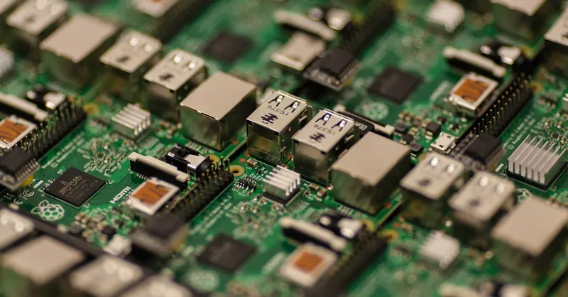
Image courtesy of Craig Dennis
Advanced Topics: DMA (Direct Memory Access) in Serial Communication for High-Speed Data Transfer
When working with high-speed serial communication on Raspberry Pi or microcontrollers, relying solely on CPU-driven data handling—whether polling or interrupts—can become a bottleneck, limiting throughput and increasing processor load. This is where Direct Memory Access (DMA) steps in as a powerful technique to offload data transfer tasks between serial peripherals and memory, enabling efficient, high-speed, and low-latency serial communication in embedded C applications.
What is DMA and Why Use It in Serial Communication?
DMA is a hardware feature that allows peripheral devices like UART, SPI, or I2C controllers to transfer data directly to or from system memory without continuous CPU intervention. Instead of the processor manually moving each byte, the DMA controller autonomously manages bulk data transfers, freeing the CPU for other critical tasks or power-saving modes.
Using DMA in serial communication offers several key advantages:
- Increased Data Throughput: Continuous data streams can be handled at much higher speeds, suitable for sensor data logging, audio streaming, or large memory transfers.
- Lower CPU Utilization: The CPU is no longer burdened by byte-wise data copying, drastically reducing interrupts and polling overhead.
- Reduced Latency and Jitter: DMA ensures timely data movement, improving real-time performance and reducing the chance of data overruns or loss.
- Efficient Buffer Management: DMA can be configured to work seamlessly with circular buffers and double-buffering techniques to maintain uninterrupted data flow.
Implementing DMA for UART/SPI/I2C in Embedded C
To harness DMA for serial communication in embedded C, you generally follow these steps:
- Configure the Serial Peripheral: Initialize the UART, SPI, or I2C interface with the desired settings (baud rate, frame format, etc.) as usual.
- Set Up DMA Channels: Assign DMA streams or channels to correspond with the serial peripheral’s transmit (TX) or receive (RX) data registers.
- Define Memory Buffers: Allocate and prepare memory buffers where incoming data will be stored or from which data will be transmitted.
- Configure DMA Transfer Parameters: Specify buffer size, data direction, increment modes, and transfer triggers tied to the serial peripheral events.
- Enable DMA Requests in Peripheral: Activate DMA mode in the serial interface so that hardware automatically triggers data transfers.
- Handle Transfer Completion via Interrupts or Polling: Optionally, use DMA interrupts to process the buffer once a transfer completes or implement double-buffering schemes for continuous streaming.
On platforms like STM32 microcontrollers, vendors provide rich DMA APIs integrated with their HAL (Hardware Abstraction Layer) libraries, simplifying the configuration. Even on Raspberry Pi, direct DMA access can boost high-speed SPI or UART data handling when interfacing with external microcontrollers or sensors.
Best Practices When Using DMA for Serial Communication
- Align Buffer Sizes: Use buffer sizes aligned to DMA hardware requirements (powers of two or specific multiples) for optimal performance.
- Manage Buffer Synchronization: Employ circular or double-buffer schemes to prevent data overwrite and ensure seamless data availability.
- Monitor Overruns and Errors: Even with DMA, always check peripheral and DMA status flags to catch transfer errors early.
- Combine with Interrupts for Control: Use lightweight interrupt service routines to signal completion or initiate subsequent transfers without taxing the CPU.
By integrating DMA-driven serial communication into your embedded C projects, you unlock unparalleled efficiency and speed, enabling your Raspberry Pi and microcontroller applications to handle demanding data transfer scenarios with minimal CPU overhead. This advanced technique is essential for professional-grade embedded systems requiring robust, high-throughput serial interfaces.

Image courtesy of Photo By: Kaboompics.com
Best Practices and Optimization Tips for Robust and Power-Efficient Serial Communication in Embedded Systems
To achieve robust and power-efficient serial communication in embedded C projects involving Raspberry Pi and microcontrollers, developers must integrate strategic best practices and optimizations that enhance reliability, reduce CPU load, and conserve energy—key factors for embedded systems operating in constrained environments. Implementing these guidelines not only improves data integrity but also extends battery life and enables scalable, maintainable designs.
Optimize Baud Rate and Frame Settings for Stability and Speed
Selecting the optimal baud rate balances communication speed with noise immunity. While higher baud rates increase throughput, they may be more susceptible to errors, especially with long cables or noisy environments. Carefully match baud rate and frame format (data bits, parity, stop bits) on both ends to eliminate framing errors and ensure smooth synchronization. Consider these tips:
- Use standard baud rates (e.g., 9600, 115200 bps) unless specific timing requirements dictate otherwise.
- Enable parity checking if error resilience is critical, but disable it in low-error, high-throughput scenarios to reduce processing overhead.
- Configure stop bits to 1 or 2 based on environmental noise and timing constraints.
Employ Interrupt-Driven Communication with Circular Buffers
To maximize CPU efficiency and responsiveness, use interrupt-driven serial communication coupled with well-designed circular buffers. This approach prevents CPU blocking from polling loops and ensures that incoming data is captured quickly without loss. Key optimization practices include:
- Keep Interrupt Service Routines (ISRs) short and fast by only reading/writing data to buffers, deferring processing to the main loop.
- Use volatile qualifiers on shared variables accessed in ISRs and main code to prevent compiler optimization issues.
- Size buffers appropriately to accommodate peak data bursts and reduce the risk of overflow.
- Monitor buffer usage and implement flow control (hardware or software) if needed to throttle data sources during high load.
Minimize Power Consumption by Selective Peripheral and CPU Usage
Power optimization is critical in battery-operated or energy-constrained embedded systems. Effective serial communication can conserve power by:
- Disabling UART peripherals when idle and re-enabling on demand to avoid unnecessary power draw.
- Configuring microcontroller low-power modes during idle intervals, waking up only on UART interrupts for data events.
- Using efficient data framing and minimal retransmissions to reduce communication duration.
- Leveraging DMA (Direct Memory Access) where available to offload data transfers and allow the CPU to enter deep sleep states.
Implement Comprehensive Error Detection and Recovery Mechanisms
Robust serial communication requires proactive error detection and graceful recovery to maintain data integrity in real-world conditions. This includes:
- Validating parity, framing, and overrun error flags on each received byte.
- Designing retransmission or handshake protocols at the application layer for critical data.
- Using watchdog timers to reset communication peripherals or entire systems upon detecting persistent faults.
- Logging or reporting error statistics to enable diagnostic insights and adaptive optimization.
Keep Code Modular and Hardware Abstraction Consistent
Maintain clean, modular embedded C code by separating hardware-specific register manipulations from protocol logic. Use hardware abstraction layers (HAL) or driver wrappers when possible to simplify portability and debugging without sacrificing low-level control. Modular design facilitates:
- Reusable serial communication interfaces across different platforms.
- Easier adaptability to protocol or peripheral changes.
- Simplified optimization focus areas such as ISR enhancements or buffer tuning.
By applying these best practices and optimization strategies, embedded developers can build robust, efficient, and power-conscious serial communication systems that enhance the performance and longevity of Raspberry Pi and microcontroller projects. Focused attention on parameter configurations, interrupt-driven designs, power management, and error handling ensures reliable data exchange essential for sophisticated embedded applications.
Image courtesy of panumas nikhomkhai