Interfacing Sensors with Raspberry Pi Using C: A Complete Guide
Category: Embedded Systems
Mastering Sensor Interfacing on Raspberry Pi with C
If you're a tech enthusiast, hobbyist, or developer eager to harness the full power of your Raspberry Pi through C programming, you've landed in the right place. Interfacing sensors with the Raspberry Pi using C isn’t just another tutorial—it’s an essential skill that bridges hardware and software elegantly, empowering you to build sophisticated embedded systems and microcontroller projects. You might already be proficient in Python or C++, but tackling sensor integration in C offers unmatched control and performance optimization, especially crucial for real-time applications or resource-constrained environments.
Perhaps you've sought straightforward, reliable methods to connect temperature, motion, or light sensors without the overhead of heavyweight libraries. Or maybe you find existing resources too generic, often diving into Python examples that don’t translate well if you prefer or require C. This guide is tailored for those exact pain points, delivering step-by-step insights, from the foundational hardware setup to robust C coding practices, all curated to accelerate your embedded programming journey.
Dive deep into GPIO handling, I2C and SPI communication protocols, sensor-specific coding, debugging strategies, and real-world project examples that reflect practical scenarios. By the end, this post won’t just equip you with code snippets; it will elevate your confidence in crafting efficient and reliable sensor-driven Raspberry Pi applications in C. Ready to push your projects beyond the usual constraints? Let’s get started.
- Mastering Sensor Interfacing on Raspberry Pi with C
- Understanding Raspberry Pi’s Hardware Interfaces Relevant to Sensors: GPIO, I2C, SPI, and UART – Overview and Use Cases
- Setting Up Your Raspberry Pi for C Programming: Installing GCC, WiringPi, and Necessary Libraries
- GPIO Basics in C: Managing Digital Input and Output for Simple Sensors
- Interfacing Analog Sensors via ADC: Techniques and C Libraries for Raspberry Pi
- Communicating with I2C Sensors Using C: Addressing, Register Access, and Data Acquisition
- SPI Protocol Sensor Interfacing in C: Initialization, Data Transfer, and Handling Multiple Devices
- Sensor Data Processing: Converting Raw Sensor Output into Meaningful Measurements in C
- Debugging and Troubleshooting Sensor Interfaces: Common Issues and Best Practices in Embedded C Development
- Building a Practical Project: Reading Temperature and Motion Sensor Data Using C on Raspberry Pi
- Optimizing Sensor Code for Performance and Power Efficiency in Embedded Systems
Understanding Raspberry Pi’s Hardware Interfaces Relevant to Sensors: GPIO, I2C, SPI, and UART – Overview and Use Cases
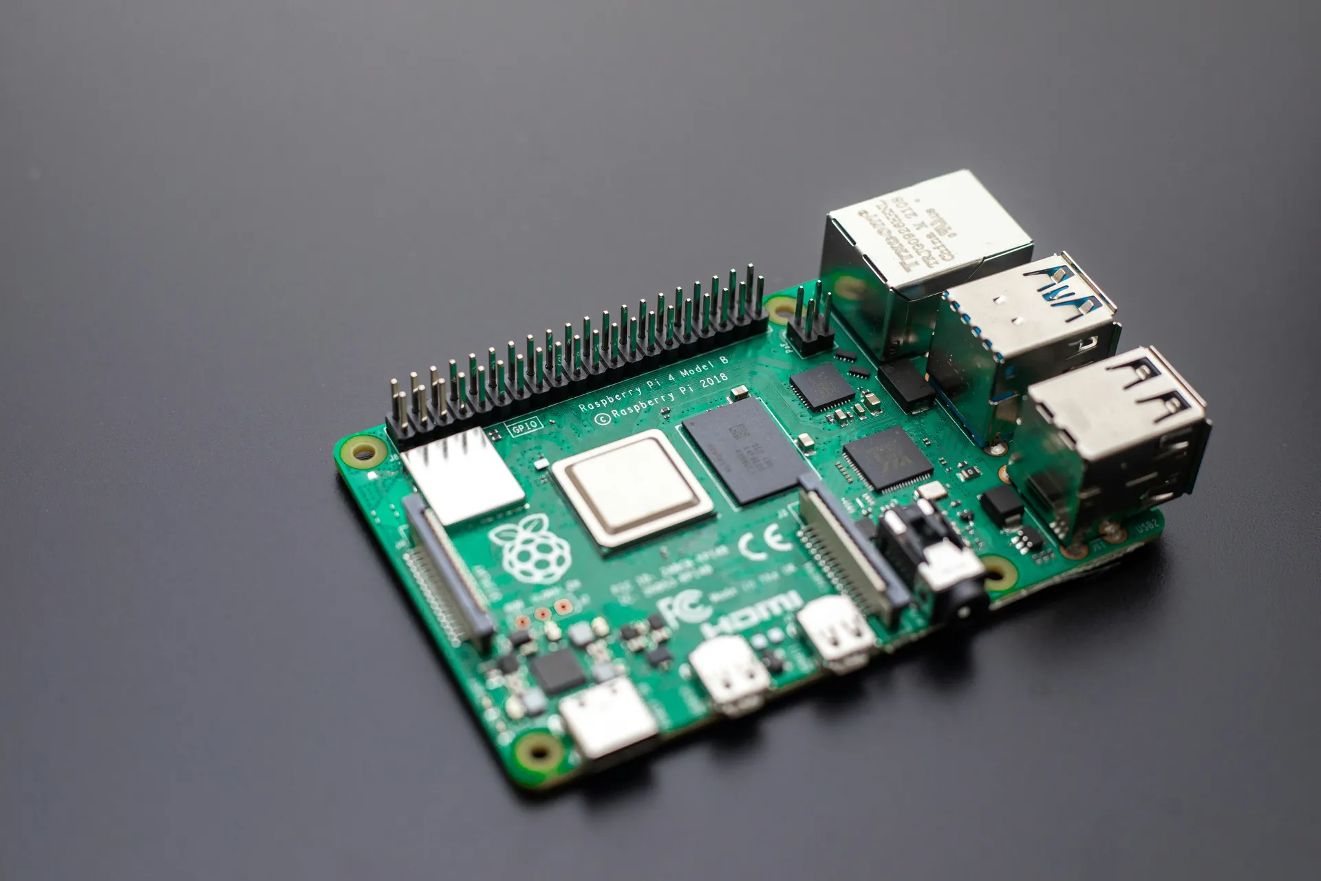
To effectively interface sensors with the Raspberry Pi using C, it’s crucial to understand the key hardware interfaces that facilitate communication between the Pi and external sensors. Each interface has unique characteristics suited for different sensor types and project requirements. These core interfaces include GPIO, I2C, SPI, and UART, and mastering their usage ensures reliable and efficient sensor data acquisition in embedded applications.
-
GPIO (General Purpose Input/Output)
GPIO pins provide the most direct and flexible way to interface with digital sensors. They can be configured as either inputs to read simple ON/OFF states (e.g., motion detectors or switches) or outputs to control actuators. GPIO is ideal for sensors that do not require complex data communication protocols. When programming in C, GPIO access involves manipulating registers or using libraries like WiringPi or bcm2835 to set pin modes and read/write digital signals with low latency. -
I2C (Inter-Integrated Circuit)
I2C is a two-wire, bus-based protocol commonly used for connecting multiple sensors such as temperature sensors (like the BMP280), accelerometers, and light sensors. Its simplicity, support for multiple devices on the same bus, and built-in addressing make it indispensable for compact, sensor-rich projects. I2C requires mastering start/stop conditions and register addressing in C, typically through Linux device files (/dev/i2c-*) or dedicated I2C libraries, enabling efficient byte-level data exchange. -
SPI (Serial Peripheral Interface)
SPI offers high-speed, full-duplex communication ideal for sensors that demand rapid data transfer or higher bandwidth, such as digital gyroscopes or ADCs. SPI uses separate lines for data in/out along with a clock and chip select, allowing precise synchronization. When working with SPI in C, you must handle chip select lines explicitly and configure clock polarity and phase, ensuring robust communication for time-sensitive sensor data. -
UART (Universal Asynchronous Receiver/Transmitter)
UART provides serial communication primarily used for sensors or modules that send data asynchronously, such as GPS receivers or certain environmental sensors. Its simple two-wire setup (TX and RX) supports long-distance communication but with lower data rates compared to SPI or I2C. Implementing UART in C involves configuring baud rates, parity, and handling data framing through Linux serial interfaces (/dev/serial0), enabling versatile sensor integration especially when working with legacy or serial-based devices.
Understanding these interfaces’ strengths and limitations helps you choose the right communication protocol tailored to your sensor’s needs and your project’s real-time constraints. Skilled C programming combined with the Raspberry Pi’s versatile hardware interfaces unlocks powerful sensor-driven embedded systems for creative prototypes and production-ready applications alike.
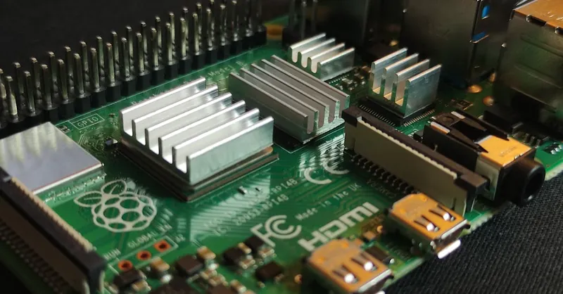
Image courtesy of Mathias Wouters
Setting Up Your Raspberry Pi for C Programming: Installing GCC, WiringPi, and Necessary Libraries
Before diving into sensor interfacing with C on your Raspberry Pi, it’s essential to prepare your development environment by installing the C compiler (GCC), sensor communication libraries like WiringPi, and other necessary tools. This setup ensures you can write, compile, and run efficient C programs that interact seamlessly with GPIO pins and communication protocols such as I2C and SPI.
Installing GCC: The Essential C Compiler
GCC (GNU Compiler Collection) is the backbone of C development on Linux-based systems like Raspberry Pi OS. To check whether GCC is installed and its version, run:
gcc --version
If it’s missing, install it along with essential build tools through:
sudo apt update
sudo apt install build-essential
This command installs GCC, make, and other utilities required for compiling C programs, ensuring you have a robust compiler for sensor interfacing projects.
WiringPi: Simplifying GPIO Access in C
Although the original WiringPi library is deprecated, it remains a lightweight and powerful tool for managing GPIO pins directly from C programs. Alternatively, you can use maintained forks or libraries like pigpio or directly access GPIO through /sys/class/gpio or libgpiod in modern systems.
To install WiringPi (or its maintained alternatives), you typically run:
sudo apt install wiringpi
For systems where WiringPi is not available, you can compile it from source or use pigpio:
sudo apt install pigpio
sudo systemctl start pigpiod
WiringPi (or its alternatives) provide C APIs to configure pin modes, read inputs, and write outputs, significantly easing GPIO programming compared to manual register manipulation.
Installing I2C and SPI Support Libraries
Many sensors rely on I2C or SPI communication, so enabling these interfaces and installing associated tools and libraries are critical steps.
- Enable Interfaces
Useraspi-configto activate I2C and SPI:
bash
   sudo raspi-config
Navigate to Interfacing Options and enable I2C and SPI.
- Install I2C Tools and Libraries
bash
   sudo apt install i2c-tools libi2c-dev
i2c-toolsallows scanning and troubleshooting I2C devices.-
libi2c-devprovides C headers and libraries required to program I2C devices using Linux device files. -
Install SPI Development Libraries
bash
   sudo apt install libspi-dev
While SPI communication is often handled via device files such as /dev/spidev0.0, having the development headers enables you to use ioctl calls in C programs for fine-grained configuration.
Additional Libraries and Tools to Consider
- BCM2835 Library: An alternative C library for direct peripheral access, including GPIO, SPI, and I2C. Ideal for performance-critical applications where low-level control is needed.
Installation example:
bash
  sudo apt install libbcm2835-dev
- Make and Debugging Tools: Utilities like
makefor automating build processes andgdbfor debugging C programs help streamline development and troubleshooting.
By thoroughly setting up your Raspberry Pi with these compilers, libraries, and tools, you lay a strong foundation for writing optimized, robust C code to interface with a wide variety of sensors. This preparation significantly accelerates development time, helping you focus on sensor logic and embedded system design instead of environment issues.

Image courtesy of Craig Dennis
GPIO Basics in C: Managing Digital Input and Output for Simple Sensors
At the heart of many sensor interfacing projects with Raspberry Pi lies the GPIO (General Purpose Input/Output) pins, which are indispensable for handling simple digital sensors. Mastering GPIO manipulation in C allows you to read signals like button presses or motion detections and control output devices such as LEDs or relays with precision and minimal latency. Unlike high-level languages such as Python, programming GPIO in C gives you granular control over pin states—ideal for embedded systems requiring deterministic behavior.
Configuring GPIO Pins for Input and Output in C
To interface with a basic sensor, the first step is configuring the appropriate GPIO pin either as an input to read data or as an output to send control signals. This setup involves:
- Exporting the Pin: Making the GPIO pin accessible via the Linux sysfs interface or using a GPIO library.
- Setting the Pin Direction: Defining the pin as
inputoroutput. - Reading or Writing Values: Polling input pins or toggling outputs.
When working directly with sysfs (deprecated in recent kernels but still widely used), this process involves file I/O on files such as /sys/class/gpio/gpioXX/direction and /sys/class/gpio/gpioXX/value. Using libraries like WiringPi, pigpio, or libgpiod simplifies these steps by providing user-friendly C functions such as digitalRead(pin) and digitalWrite(pin, value).
Handling Digital Inputs: Reading Sensor States
Reading digital sensors involves continuously or periodically checking the GPIO pin voltage level—LOW (0) or HIGH (1). Common simple sensors include:
- Push Buttons: Detecting user input.
- PIR Motion Sensors: Triggering alerts on movement.
- Reed Switches: Sensing magnetic fields.
Polling input pins in C requires minimal CPU overhead if optimized properly and can be enhanced with interrupt-driven GPIO if supported, using edge detection callbacks to respond instantly without busy-waiting.
Driving Outputs: Controlling Devices Based on Sensor Data
Output pins allow you to actuate devices depending on sensor feedback. For instance, turning on an LED when motion is detected or activating a buzzer if a limit switch is pressed. In C, writing a HIGH or LOW state to an output pin is as straightforward as calling a dedicated function or writing the corresponding value to the GPIO's value file.
By deeply understanding and utilizing GPIO programming in C, you unlock the potential to seamlessly integrate a multitude of simple digital sensors with your Raspberry Pi, laying a vital foundation before moving onto more complex I2C or SPI sensor protocols. This grasp elevates your embedded systems projects with efficient, low-level hardware interaction tailored for performance-critical applications.

Image courtesy of Craig Dennis
Interfacing Analog Sensors via ADC: Techniques and C Libraries for Raspberry Pi
Unlike digital sensors that communicate directly via GPIO, I2C, or SPI, many real-world sensors output analog signals, such as varying voltage levels representing temperature, light intensity, or pressure. Since the Raspberry Pi’s GPIO pins lack built-in Analog-to-Digital Conversion (ADC) capabilities, reading analog sensor data requires integrating an external ADC chip or module. Mastering how to interface analog sensors with Raspberry Pi using C involves understanding different ADC techniques, choosing compatible ADC hardware, and leveraging effective C libraries to acquire and process analog data accurately.
Methods to Interface Analog Sensors with Raspberry Pi
-
Using External ADC Chips over SPI or I2C:
Popular ADC ICs like the MCP3008 (SPI) or ADS1115 (I2C) convert analog signals into digital values readable by the Raspberry Pi through their respective communication protocols. This approach is reliable for high-resolution and multi-channel analog sensing. In C programming, you interact with these ADCs by writing SPI or I2C communication routines that send control commands and read digital results using Linux device files (/dev/spidev*or/dev/i2c-*) or dedicated libraries. -
Employing ADC Hat or Modules:
Plug-and-play ADC hats simplify hardware setup, providing ready-to-use ADC interfaces. These often include example C APIs or support libraries optimized for Raspberry Pi, reducing development time. -
Using Arduino or Microcontroller as ADC Bridge:
For complex multi-sensor projects, an Arduino or microcontroller can perform ADC conversion and send digitized data to Raspberry Pi via serial or USB, enabling flexible analog sensing with C or Python on the Pi receiving processed values.
Key C Libraries and APIs for ADC Interfacing
-
WiringPi ADC Interface: Provides simple SPI communication functions to read from ADCs like MCP3008, ideal for beginners and quick prototypes.
-
BCM2835 Library: Offers low-level SPI/I2C control ideal for custom ADC communication with precise timing.
-
libi2c-dev and Linux SPI ioctl APIs: Standard Linux interfaces accessed via C for communication with I2C/SPI ADC devices without third-party dependencies.
-
ADS1x15 C Driver: Open-source drivers exist for ADCs like ADS1115, simplifying register configuration and raw data retrieval.
Implementing ADC Readings in C: General Workflow
-
Initialize Communication: Open and configure the SPI or I2C device file with correct mode, speed, and settings.
-
Send ADC Command: Transmit start bits and channel selection bytes to specify which analog input to read.
-
Read Digital Data: Retrieve the converted digital value that corresponds to the analog input voltage.
-
Process Data: Convert raw ADC counts into meaningful physical units (e.g., temperature in °C) through calibration equations or datasheet formulas.
By leveraging these techniques and tools, you can accurately integrate a vast range of analog sensors within your Raspberry Pi projects, expanding sensory capabilities beyond digital inputs. This approach not only enriches your embedded systems portfolio but also optimizes sensor data fidelity, crucial for precision measurement and control applications programmed efficiently in C.
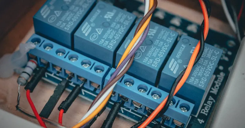
Image courtesy of Malte Luk
Communicating with I2C Sensors Using C: Addressing, Register Access, and Data Acquisition
Interfacing I2C sensors with your Raspberry Pi in C unlocks the ability to communicate with a vast ecosystem of devices—including temperature sensors, accelerometers, and digital compasses—through a simple two-wire bus. Mastering I2C communication requires understanding sensor addressing, register-level data access, and efficient data acquisition techniques within the Linux environment, all crucial for robust embedded system design.
Understanding I2C Device Addressing
Every I2C sensor on the bus is uniquely identified by a 7-bit or 10-bit address, which your C program must target when initiating communication. Most Raspberry Pi I2C devices use 7-bit addressing, and you can discover connected devices using the following command-line tool:
i2cdetect -y 1
This displays a grid revealing active sensor addresses on bus 1 (/dev/i2c-1), which you'll use as the device identifier in your C code. Proper addressing is vital since multiple sensors share the same bus, avoiding conflicts and ensuring commands reach the correct device.
Accessing Sensor Registers via I2C in C
I2C communication fundamentally revolves around reading and writing data to specific sensor registers, which control sensor settings or hold measurement values. To perform these operations in C, you typically follow this workflow:
-
Open the I2C Device File
Access/dev/i2c-1using theopen()system call. -
Set the Slave Address
Use theioctl()system call withI2C_SLAVEto specify the target sensor’s address. -
Read/Write Registers
- Write the target register address to select the internal sensor register.
- Perform a subsequent read or write operation to transfer sensor data.
Here’s a simplified example pattern for reading a register:
int file = open("/dev/i2c-1", O_RDWR);
ioctl(file, I2C_SLAVE, sensor_address);
// Write register address to sensor
unsigned char reg = REGISTER_ADDRESS;
write(file, ®, 1);
// Read data from register
unsigned char data[2];
read(file, data, 2);
Acquiring and Interpreting Sensor Data Efficiently
Efficient data acquisition often involves reading multiple bytes from consecutive registers in a single transaction, reducing bus overhead and ensuring data consistency—critical for sensors that store values in high and low bytes or have status flags. After retrieving raw data, apply calibration or conversion formulas from the sensor datasheet to translate raw counts into human-readable physical units like °C, lux, or g-force.
To optimize this process:
- Use repeated start conditions when writing register addresses immediately followed by reading data without releasing the bus.
- Implement error handling to detect and recover from bus contention or communication failures.
- Consider buffered reads/writes and adhere to sensor-specific timing requirements for sampling stability.
By mastering these concepts of I2C addressing, register manipulation, and data acquisition in C, you gain fine-grained control over sensor interactions on the Raspberry Pi. This enables you to create highly responsive and precise embedded applications that fully exploit your sensors’ capabilities while ensuring reliability and performance in resource-constrained environments.

Image courtesy of Alessandro Oliverio
SPI Protocol Sensor Interfacing in C: Initialization, Data Transfer, and Handling Multiple Devices
The Serial Peripheral Interface (SPI) protocol stands out as a high-speed, synchronous communication method widely used for sensor interfacing on the Raspberry Pi, especially when your project demands rapid data transfer and precise timing. Programming SPI in C offers you fine-grained control over chip select lines, clock polarity, phase, and data order—crucial for ensuring reliable communication with various SPI-based sensors such as digital gyroscopes, ADCs, and environmental monitors.
Initializing SPI Communication on Raspberry Pi Using C
To establish SPI communication in C, you begin by opening the relevant SPI device file (commonly /dev/spidev0.0 or /dev/spidev0.1). Initialization involves configuring SPI parameters using ioctl system calls:
- SPI Mode: Select clock polarity (CPOL) and clock phase (CPHA) to match the sensor’s timing requirements.
- Bits per Word: Usually set to 8 bits, but some devices might require different word lengths.
- Max Speed (Hz): Define the SPI clock frequency to balance speed and signal integrity.
Example initialization snippet:
int fd = open("/dev/spidev0.0", O_RDWR);

uint8_t mode = SPI_MODE_0; // CPOL=0, CPHA=0
uint8_t bits = 8;
uint32_t speed = 500000;

ioctl(fd, SPI_IOC_WR_MODE, &mode);
ioctl(fd, SPI_IOC_WR_BITS_PER_WORD, &bits);
ioctl(fd, SPI_IOC_WR_MAX_SPEED_HZ, &speed);
Establishing these parameters correctly is vital to prevent data corruption or communication failures, tailoring the interface to the sensor’s datasheet specifications.
Managing Data Transfer: Full-Duplex SPI Communication in C
SPI inherently supports full-duplex data exchange, meaning you send and receive data simultaneously over separate MOSI (Master Out Slave In) and MISO (Master In Slave Out) lines. In C, this is typically managed via the spi_ioc_transfer structure and the corresponding ioctl call, which allows atomic SPI transactions transferring data buffers of arbitrary length.
Key points for robust SPI data transfer:
- Prepare transmit and receive buffers: Organize outgoing command or register address bytes and allocate space for incoming sensor data.
- Use
spi_ioc_transferstruct appropriately: Set pointers to tx and rx buffers, the transfer length, speed, delay, and bits per word. - Handle timing-sensitive commands: Consider sensor-specific requirements for delays or repeated transactions.
Example transaction setup:
struct spi_ioc_transfer tr = {
    .tx_buf = (unsigned long)tx_buffer,
    .rx_buf = (unsigned long)rx_buffer,
    .len = buffer_length,
    .speed_hz = speed,
    .bits_per_word = bits,
};

ioctl(fd, SPI_IOC_MESSAGE(1), &tr);
This approach ensures that sensor commands and responses are synchronized and received accurately, essential for high-fidelity sensor data acquisition.
Handling Multiple SPI Devices: Chip Select Management and Bus Sharing
When multiple SPI sensors share the same bus on the Raspberry Pi, careful management of Chip Select (CS) signals and bus arbitration is imperative. The Raspberry Pi provides hardware-controlled chip selects (/dev/spidev0.0 and /dev/spidev0.1), but for projects with more SPI devices than hardware CS lines, you must handle additional CS pins manually via GPIO.
Strategies to handle multiple SPI devices include:
- Use hardware CS lines for up to two devices: Utilize
/dev/spidev0.0and/dev/spidev0.1to target sensors with dedicated chip selects. - Manually control GPIO pins as CS: For additional devices, configure GPIO outputs to serve as custom chip select lines, toggling them programmatically in C to activate desired sensors.
- Implement exclusive bus access: Ensure that only one device’s CS line is asserted during each SPI transaction to prevent bus contention.
- Create modular driver functions: Encapsulate SPI transfers with chip select control for each sensor device to streamline code reuse and maintainability.
By mastering SPI initialization, full-duplex data transfer, and chip select management in C, you unlock the ability to integrate multiple high-speed sensors seamlessly, optimizing performance and reliability in your Raspberry Pi embedded applications. This expertise empowers complex sensor fusion projects and real-time data processing scenarios that demand precision and low latency combined with robust hardware-software synchronization.

Image courtesy of Alessandro Oliverio
Sensor Data Processing: Converting Raw Sensor Output into Meaningful Measurements in C
Once you have successfully acquired raw data from your sensors via GPIO, I2C, SPI, or ADC interfaces on the Raspberry Pi, the next critical step is processing this raw sensor output into actionable, meaningful measurements. Effective sensor data processing in C involves converting the sensor’s digital or analog values—often represented as raw counts, voltage levels, or bit patterns—into standardized physical units such as degrees Celsius, meters per second squared, or lumens. This transformation is essential for developing responsive embedded systems and reliable control applications.
Key Steps in Sensor Data Conversion and Processing
-
Understanding Sensor Data Format and Calibration
Each sensor model outputs data according to its own specific format and scale, typically detailed in its datasheet. For most sensors, raw readings need to be adjusted using calibration constants such as scale factors, offsets, or lookup tables. In C, this means implementing precise mathematical formulas that translate raw ADC counts or read register values into real-world units, ensuring accuracy and consistency. -
Data Scaling and Unit Conversion in C
After reading the raw sensor data (e.g., a 12-bit ADC value), apply scaling equations:
c
   float voltage = (raw_adc_value / (float)ADC_MAX_COUNT) * VREF;
   float temperature_c = (voltage - TEMP_SENSOR_OFFSET) / TEMP_SENSOR_SLOPE;
This approach transforms abstract raw numbers into physical quantities, enabling your application to make meaningful decisions based on real-world environmental changes.
-
Filtering and Noise Reduction
Sensor signals are often noisy due to environmental interference or electrical fluctuations. Implementing simple filters like moving average, low-pass filters, or more advanced digital filtering methods directly in C improves data stability and measurement reliability without incurring external library dependencies. -
Multi-byte Data Parsing and Endianness Handling
Many sensors transmit measurements across multiple bytes that must be combined correctly. Pay attention to byte order (endianness) and signed or unsigned representations when reconstructing numerical values from sensor registers to avoid misinterpretations. -
Error Checking and Data Validation
Always validate sensor readings against expected ranges or status flags to detect faulty measurements or communication errors. Implementing error handling in your C code prevents spurious data from propagating through your system, enhancing robustness.
Best Practices for Effective Sensor Data Processing in Embedded C
- Implement Modular Functions: Design reusable C functions for data conversion tailored to each sensor type, which simplifies code maintenance and encourages scalability.
- Leverage Fixed-Point Arithmetic: Where MCU resources are limited, consider using fixed-point math to boost performance and reduce floating-point overhead.
- Document Calibration Parameters Clearly: Store constants and conversion coefficients consistently, ideally in configuration headers or external files, enabling easy adjustments without deep code changes.
- Test with Known Reference Values: Validate your processing code against sensor datasheet examples or calibrated measurement tools to ensure accuracy.
By mastering these sensor data processing techniques in C, you elevate your Raspberry Pi projects from raw data collection to insightful, precision-driven embedded solutions. This competency not only enhances sensor fusion and control effectiveness but also optimizes system responsiveness, setting the stage for sophisticated IoT devices and real-time monitoring applications.
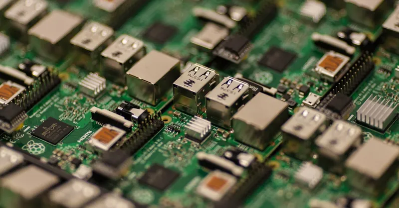
Image courtesy of Craig Dennis
Debugging and Troubleshooting Sensor Interfaces: Common Issues and Best Practices in Embedded C Development
When interfacing sensors with the Raspberry Pi using C, encountering communication glitches, inaccurate readings, or unexpected behaviors is common, especially in complex embedded environments. Mastering effective debugging and troubleshooting techniques is essential to pinpoint hardware and software issues quickly, ensuring your sensor integration is both reliable and performant.
Common Issues in Sensor Interfacing on Raspberry Pi Using C
-
Incorrect Wiring and Hardware Faults
Faulty or loose connections, wrong pin assignments, or power supply problems are the leading causes of sensor malfunctions. Always verify GPIO, I2C, SPI, or UART connections against Raspberry Pi pinout diagrams and sensor datasheets before debugging code. -
Addressing and Configuration Errors
I2C sensor address mismatches or SPI mode misconfigurations (clock polarity and phase) frequently lead to no communication or garbled data. Double-check sensor addresses with tools likei2cdetectand validate SPI settings align precisely with sensor specifications. -
Permission and Access Issues
Accessing hardware device files such as/dev/i2c-1or/dev/spidev0.0requires proper user permissions. Running your C programs without sufficient privileges or without enabling necessary interfaces inraspi-configcan cause failures. -
Timing and Protocol Mismanagement
Violating required sensor timing, ignoring repeated start conditions in I2C, or mishandling chip select lines in SPI can corrupt data exchanges. Timing-sensitive sensors often require delays or atomic operations that must be carefully implemented in C code. -
Data Interpretation Errors
Misalignment in multi-byte reads, incorrect endianness handling, or ignoring sensor calibration constants can yield invalid measurement outputs. Ensuring your data parsing logic matches the sensor datasheet format is critical.
Best Practices for Debugging Sensor Interfaces in Embedded C on Raspberry Pi
-
Leverage Diagnostic Tools: Use Linux command-line utilities like
i2cdetect,i2cdump, andspidev_testto verify device presence and basic communication before writing code. -
Incremental Code Testing: Develop sensor communication in small independent steps—first initialize interfaces, then test register reads/writes, followed by data processing—facilitating isolated troubleshooting.
-
Robust Error Handling: Always check return values from system calls like
open(),ioctl(),read(), andwrite()to detect failures early, allowing graceful recovery or informative logging. -
Implement Logging and Verbose Output: Integrate detailed debug print statements or write logs to files for inspection of transmitted and received bytes, addressing, and error codes during runtime.
-
Use Oscilloscopes or Logic Analyzers: For hardware-level issues, tools like logic analyzers help visualize I2C or SPI signals, identify glitches, and confirm electrical correctness.
-
Explore Cross-Referencing Datasheets: Review both Raspberry Pi peripherals and sensor datasheets to understand electrical characteristics, timing diagrams, and communication protocol nuances thoroughly.
By adopting these best practices in debugging and troubleshooting, you accelerate development cycles and enhance the stability of your Raspberry Pi sensor projects programmed in C. This solid foundation empowers you to build robust embedded systems capable of handling real-world uncertainties with confidence and precision.

Image courtesy of Alessandro Oliverio
Building a Practical Project: Reading Temperature and Motion Sensor Data Using C on Raspberry Pi
To consolidate your understanding of sensor interfacing via C, let’s build a practical example that reads data from two common sensors: a temperature sensor (e.g., TMP102 or DS18B20) and a PIR motion sensor. This project demonstrates real-world integration by combining digital GPIO handling and I2C communication within a single C program running on Raspberry Pi, showcasing efficient sensor data acquisition and processing.
Hardware Setup Overview
-
Temperature Sensor (I2C-based TMP102 or similar):
Connected via the Raspberry Pi’s I2C bus (SDAandSCLpins), this sensor provides precise temperature readings. Ensure the I2C interface is enabled on your Pi and the sensor address is properly detected withi2cdetect. -
PIR Motion Sensor (Digital GPIO):
Wired to a digital GPIO input pin, the PIR sensor outputs a HIGH signal upon detecting motion. This sensor illustrates handling digital input signals in C with low latency.
Implementing the C Program
- Initialize Interfaces:
- Open the I2C device file (typically
/dev/i2c-1) and set the slave address to the temperature sensor’s address. -
Set up the GPIO pin connected to the PIR sensor as an input using your GPIO library or sysfs interface.
-
Reading Temperature Data via I2C:
- Write the temperature register address to the sensor.
- Read the data bytes representing the temperature.
-
Convert the raw I2C data into a human-readable Celsius value applying the sensor’s conversion formula.
-
Polling the PIR Sensor State:
- Continuously read the digital input pin connected to the PIR sensor.
-
Detect rising edges indicating motion events and trigger corresponding actions such as printing alerts or activating an output.
-
Integration Loop:
- Combine temperature readings taken at defined intervals (e.g., once per second) with frequent PIR state checks (e.g., every 100ms) within a loop.
- Implement non-blocking delays or timer mechanisms to efficiently handle diverse sensor polling rates, preserving system responsiveness.
Essential Programming Considerations
-
Error Handling:
Check return values from all I2C and GPIO operations robustly to handle bus errors, device disconnections, or permission issues gracefully. -
Performance Optimization:
Use buffered reads/writes and minimize I2C transactions to reduce overhead. Debounce the PIR sensor input in software to avoid false triggers. -
Scalable Code Structure:
Modularize separate functions for I2C temperature reads and GPIO motion checks, enabling future expansion such as adding logging, alerts, or additional sensor inputs.
By developing this foundational project, you gain invaluable hands-on experience combining sensor communication protocols and GPIO digital input handling in C on Raspberry Pi. This approach is highly extensible, serving as a blueprint for sophisticated real-time monitoring systems, home automation, or environmental sensing applications—all written in efficient, low-level C code for high performance and reliability.

Image courtesy of Jakub Zerdzicki
Optimizing Sensor Code for Performance and Power Efficiency in Embedded Systems
When developing sensor applications on the Raspberry Pi using C, optimizing your code for performance and power efficiency is critical—especially in embedded systems where resources are limited and responsiveness is paramount. Efficient sensor interfacing not only ensures faster data acquisition and processing but also extends the operational lifetime of battery-powered devices and reduces system thermal overhead.
Strategies for High-Performance Sensor Code in C
-
Minimize System Calls and I/O Overhead
Frequent interactions with device files like/dev/i2c-1or/dev/spidev0.0can introduce latency. Buffer data transfers where possible, and batch multiple sensor register reads/writes in a single transaction to reduce bus contention and context switches. -
Use Interrupt-Driven GPIO Instead of Polling
Rather than continuously polling GPIO pins for sensor state changes—which is CPU-intensive—leverage edge-triggered interrupts to react precisely when inputs change. In C, this reduces CPU usage drastically and improves system responsiveness for sensors like PIR motion detectors. -
Optimize Communication Parameters
Fine-tune I2C bus speed, SPI clock frequency, and SPI mode settings to match sensor capabilities and environmental conditions. Running the bus at the highest stable speed supported reduces overall transaction time and frees up CPU cycles. -
Implement Efficient Data Processing Algorithms
Use lightweight math operations, fixed-point arithmetic, and avoid floating-point computations when possible to save CPU cycles and reduce code size. Apply filtering algorithms that balance noise reduction with computational demand, such as simple moving averages or exponential filters implemented in C. -
Cache and Reuse Sensor Data
For sensors with slow-changing outputs, avoid redundant sensor reads by implementing caching mechanisms and only polling when necessary or after expiration of a validity period.
Power Efficiency Best Practices
-
Reduce Peripheral Power Usage
Disable unused interfaces like I2C or SPI when idle. Configure GPIO pins to low-power states to minimize leakage currents. -
Utilize Sleep Modes and Delays
Insert appropriate sleep intervals in your C program during idle periods or between sensor polling cycles to reduce CPU activity and power draw without sacrificing responsiveness. -
Batch Sensor Reads and Optimize Polling Intervals
Design your sensor read cycles to consolidate operations and extend the interval between communications, balancing timely data updates with energy consumption.
Summary of Key Optimization Benefits
| Optimization Technique | Impact on Embedded Sensor Systems |
|---|---|
| Interrupt-driven GPIO handling | Reduces CPU load; instantaneous sensor event detection |
| Batched I2C/SPI transactions | Minimizes communication overhead; improves throughput |
| Fixed-point arithmetic and filtering | Lower CPU usage; faster sensor data processing |
| Power management through sleep modes | Extended battery life; lower thermal output |
By integrating these performance and power optimization techniques into your C sensor interface code on the Raspberry Pi, you enhance system efficiency—achieving faster, more reliable data acquisition while conserving energy. This not only benefits real-time embedded applications but also improves scalability and deployment possibilities for sensor-rich IoT solutions and long-term monitoring systems.
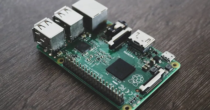
Image courtesy of Alessandro Oliverio