Master Debugging Raspberry Pi Hardware Projects Effectively
Category: Embedded Systems
Debugging Raspberry Pi Hardware Projects: Step Up Your Skills
For tech enthusiasts, hobbyists, and developers immersed in Raspberry Pi and microcontroller projects, hitting a hardware snag can be both frustrating and a major time sink. Whether you are wiring up sensors, integrating new peripherals, or working on embedded systems with Python or C/C++, the need to find and fix hardware issues efficiently is paramount. You've landed here because you want practical, hands-on strategies to unravel complex hardware problems rather than generic advice. This guide is designed specifically for your level—assuming you know your way around Raspberry Pi basics but seek deeper insights to turbocharge your debugging process. We’ll walk through systematic troubleshooting methods, essential diagnostic tools, common hardware pitfalls, and best practices that seasoned developers swear by. Unlike scattered forum posts or cryptic manuals, this post structures your entire debugging workflow in one spot, optimized for clarity and action. By the end, you’ll not only debug smarter but also design with fewer issues, freeing more time for creative coding and project expansion. Get ready to transform how you handle Raspberry Pi hardware issues and build projects with confidence and ease.
- Debugging Raspberry Pi Hardware Projects: Step Up Your Skills
- Understanding Common Hardware Issues in Raspberry Pi Projects
- Essential Tools and Equipment for Hardware Debugging
- Systematic Troubleshooting Workflow
- Analyzing and Verifying Power Supply and Voltage Regulation
- Debugging Peripheral and GPIO Interface Problems
- Using Serial Console and UART for Low-Level Debugging
- Detecting and Resolving Interference and Noise Issues
- Firmware and Driver Checks Impacting Hardware Functionality
- Preventive Practices and Documentation for Easier Debugging
- Resources and Advanced Techniques for Continuous Learning
Understanding Common Hardware Issues in Raspberry Pi Projects
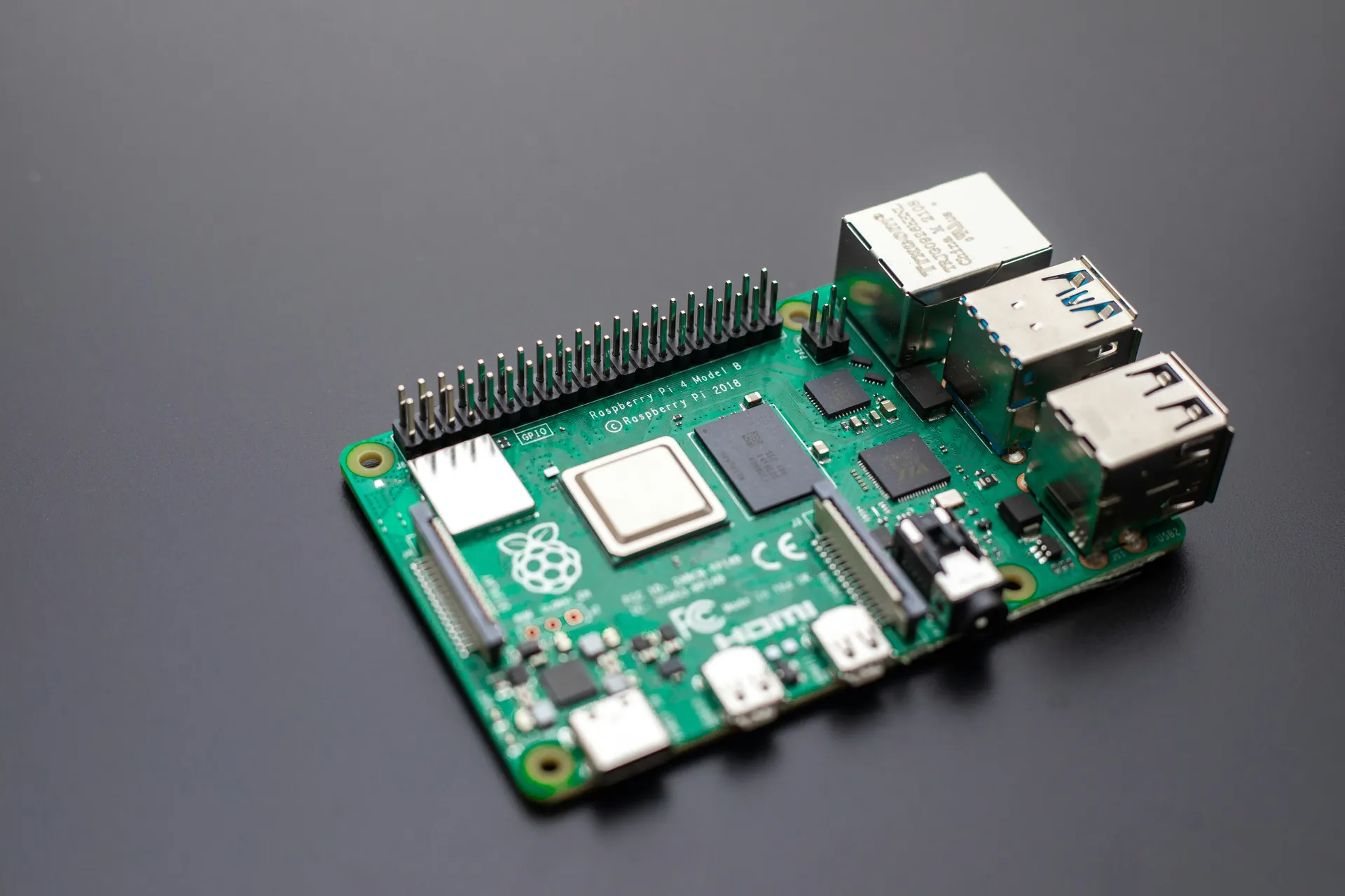
When working on Raspberry Pi hardware projects, encountering common issues like power supply glitches, faulty wiring, peripheral conflicts, and boot failures can derail your progress. Recognizing these typical problems early can save valuable troubleshooting time and prevent unnecessary component replacements.
-
Power Supply Glitches
The Raspberry Pi demands a stable, adequate power source—usually 5V with at least 2.5A current for recent models. Insufficient or unstable power often leads to random reboots, undervoltage warnings, or failure to boot. Common culprits include low-quality USB chargers, long or thin cables causing voltage drops, and power surges from connected peripherals. Always use a trusted power supply and check for voltage drop issues with a multimeter or built-in system logs. -
Faulty Wiring and Connections
Loose jumper wires, incorrect GPIO pin connections, or poorly soldered headers can result in intermittent device behavior or complete failure. Debugging wiring issues involves methodical verification: consult the Raspberry Pi pinout diagram, check connections twice, and test each component individually. Remember, even a single misplaced wire can cause sensor data to be corrupted or peripherals to stop functioning. -
Peripheral and Hardware Conflicts
Connecting multiple modules can cause resource clashes, such as I2C address conflicts or SPI bus collisions. For example, two I2C sensors with identical addresses will interfere, leading to communication failures. Always verify the compatibility of peripherals, configure unique addresses when possible, and review system logs for error messages indicating bus conflicts. -
Boot Failures and SD Card Issues
Failure to boot is a common and frustrating symptom, often linked to corrupted or improperly flashed SD cards. Ensure you use high-quality SD cards verified for Raspberry Pi use, and always safely eject and power down before removing them. Boot problems can also arise from incompatible OS images, missing files, or faulty hardware. Observing the onboard LEDs during boot can give clues—blinking patterns often indicate specific errors.
By mastering the identification of these frequently encountered hardware issues, you'll enhance your troubleshooting efficiency and reduce downtime. Incorporating systematic checks at each step of your Raspberry Pi project development ensures smoother builds and more reliable deployments.

Image courtesy of Nic Wood
Essential Tools and Equipment for Hardware Debugging
Equipping yourself with the right tools and diagnostic equipment is crucial to efficiently identify and resolve hardware issues in your Raspberry Pi projects. Whether you're working on sensor integration, peripheral communication, or power management, having these essential instruments at hand will save you countless hours of guesswork and trial-and-error.
1. Multimeters: The Fundamental Diagnostic Tool
A digital multimeter (DMM) is indispensable for checking voltages, resistances, and continuity in your circuits. Use it to verify power supply levels, detect short circuits, and confirm proper wiring connections. When troubleshooting, a quick voltage check at the GPIO pins or power terminals can instantly reveal undervoltage conditions or wiring faults. Advanced multimeters with capacitance and frequency measurement add further versatility to your Raspberry Pi debugging arsenal.
2. Oscilloscopes: Visualize Signal Integrity
An oscilloscope allows you to observe the exact waveform of digital or analog signals in real time. This capability is invaluable for checking clock signals, data communications (like SPI or I2C), and detecting noise or interference affecting sensor outputs. Modern USB oscilloscopes are affordable and compact, making them accessible tools for hobbyists and developers looking to validate timing and signal quality in embedded systems.
3. Logic Analyzers: Decoding Digital Communication
When dealing with complex peripherals or bus protocols, a logic analyzer can decode digital signals and capture communication sequences between your Raspberry Pi and connected devices. It helps pinpoint problems like address conflicts, incorrect command sequences, or timing errors on protocols such as I2C, SPI, UART, or PWM. Software-integrated logic analyzers with graphical interfaces enable easier interpretation of signal data, streamlining protocol-level debugging.
4. Software Utilities for Hardware Inspection
Beyond physical tools, leveraging software diagnostic utilities enhances your hardware troubleshooting process. Tools like vcgencmd provide Raspberry Pi-specific hardware status information, including thermal readings and voltage conditions. Serial console logs and kernel messages (dmesg) offer insights into peripheral initialization failures or driver conflicts. Additionally, Python and C/C++ debugging libraries can help test and validate hardware interface code, correlating software behavior with hardware performance.
By integrating these core debugging tools and utilities into your workflow, you can quickly isolate and address hardware faults, optimize your Raspberry Pi project development, and significantly reduce downtime. Investing time to master these instruments pays off with smoother hardware integrations and more reliable embedded system builds.

Image courtesy of IT services EU
Systematic Troubleshooting Workflow
A systematic troubleshooting workflow is essential for efficiently diagnosing and resolving hardware issues in Raspberry Pi projects. Rather than relying on guesswork or random fixes, following a step-by-step approach helps isolate problems methodically, saving time and reducing frustration. This workflow consists of several key stages:
1. Isolation: Narrow Down the Faulty Component or Subsystem
Start by simplifying your setup to identify the root cause. Disconnect all non-essential peripherals, cables, and sensors, then test the Raspberry Pi’s core functions. Gradually reintroduce each component one at a time, verifying operation after every addition. This divide-and-conquer technique helps pinpoint if the fault lies in the power supply, wiring, peripheral modules, or software interfaces.
2. Hypothesis Testing: Formulate and Verify Assumptions
Once you have isolated a potential fault area, form hypotheses based on observed symptoms. For example, if your sensor data is erratic, suspect wiring errors or I2C address conflicts. Test each hypothesis using appropriate diagnostic tools such as a multimeter for voltage checks, logic analyzers to monitor bus communication, or software logs to inspect driver errors. Systematically confirm or disprove each assumption to focus your repair efforts.
3. Checking Power Lines: Ensure Stable and Adequate Power
Verify the power integrity by measuring voltages on the 5V and 3.3V lines using your multimeter. Check for voltage drops, noise, or fluctuations when peripherals are engaged. An unstable power source often causes reboot loops or peripheral malfunctions. Confirm that the power supply and cables meet the Raspberry Pi’s specifications and that USB peripherals do not draw excessive current beyond recommended limits.
4. Verifying Component Compatibility: Avoid Conflicts and Failures
Cross-check the datasheets and specifications of all connected components to ensure they are compatible with the Raspberry Pi’s voltage levels, protocols, and pin configurations. Pay special attention to communication buses like I2C and SPI—avoid address duplication and bus contention by configuring unique addresses or using multiplexers when needed. Incompatible components often manifest as non-responsive devices or erratic signals, and careful verification prevents such issues.
Adopting this systematic troubleshooting workflow, combining isolation, targeted hypothesis testing, power verification, and compatibility checks, will drastically improve your Raspberry Pi hardware debugging success rate. Not only will this disciplined process reduce downtime, but it will also deepen your understanding of embedded systems design, leading to more robust and scalable projects.
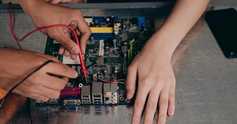
Image courtesy of Mikhail Nilov
Analyzing and Verifying Power Supply and Voltage Regulation
A stable and well-regulated power supply is the backbone of any reliable Raspberry Pi hardware project. Fluctuations in voltage or inadequate current delivery not only cause erratic system behavior, such as unexpected reboots and data corruption, but can also damage sensitive components and connected peripherals. Therefore, thoroughly analyzing your power source and verifying voltage regulation is crucial in the debugging process.
Stabilizing Power Sources for Your Raspberry Pi
Start by selecting a high-quality power supply that meets or exceeds the official Raspberry Pi recommendations—generally a 5V supply capable of delivering at least 2.5A for modern Pi models. Avoid generic phone chargers or low-rating USB supplies, as they often cannot consistently maintain the required voltage under load. Additionally, pay close attention to the power delivery path:
- Use short, thick-gauge USB cables or dedicated power cables to minimize voltage drops.
- Opt for powered USB hubs when connecting multiple peripherals to reduce current strain on the Pi’s onboard regulator.
- Consider adding a power management IC or a UPS Hat to protect against sudden power losses and to stabilize input voltage.
Detecting Undervoltage Conditions and Drops
The Raspberry Pi firmware and Linux kernel include built-in diagnostics that can detect undervoltage events. Using the command:
vcgencmd get_throttled
you can check if your Pi has experienced undervoltage (bit 0x1) or frequency capping due to insufficient power. Complement this system-level monitoring with manual measurements:
- Use a multimeter to measure the voltage at the Pi’s 5V and 3.3V pins under idle and loaded conditions.
- Identify voltage drops when peripherals activate, which often indicate power supply limits or cable issues.
- For in-depth analysis, an oscilloscope can reveal voltage ripple or noise that may destabilize communications or sensors.
Protecting Your Pi and Peripherals from Power Issues
To safeguard your Raspberry Pi and connected devices, implement power protection strategies such as:
- Adding fuses or PTC resettable fuses on the power lines to prevent damage from short circuits or overcurrent situations.
- Integrating voltage regulators or DC-DC converters with adequate current ratings for custom power sources.
- Using capacitors at power input points to smooth transient voltage dips, especially in high-current or motor-driven projects.
- Applying ESD protection on exposed GPIO pins or peripheral connections to prevent static discharge damage.
By proactively stabilizing power supplies, continuously monitoring for undervoltage conditions, and incorporating hardware safeguards, you ensure your Raspberry Pi runs reliably and your projects enjoy longer lifespans with minimal unexpected failures. This vigilance in power supply analysis is a fundamental pillar of successful Raspberry Pi hardware debugging and embedded system stability.

Image courtesy of ThisIsEngineering
Debugging Peripheral and GPIO Interface Problems
When working with Raspberry Pi projects, GPIO pins and peripheral interfaces are common sources of debugging headaches. Faulty connections, signal integrity issues, or misconfigured pins can lead to unresponsive sensors, erratic data, or complete communication failure. Mastering the fundamentals of checking pin connections, verifying signal quality, and identifying common GPIO misconfigurations using both DIY methods and specialized debug utilities drastically improves your troubleshooting effectiveness.
Checking Pin Connections and Wiring Accuracy
The first step in diagnosing GPIO-related problems is a detailed physical inspection of your wiring:
- Verify the Pinout: Always cross-reference your wiring with the latest Raspberry Pi GPIO pinout diagram, as pin functions vary across Pi models (e.g., Raspberry Pi 3 vs 4).
- Inspect for Loose or Reversed Wires: Use a multimeter’s continuity mode to confirm that each GPIO pin connects correctly to your sensor or peripheral, and that ground lines are properly shared.
- Avoid Direct 5V Signals: Many peripherals operate at 5V logic, but Raspberry Pi GPIO is 3.3V tolerant only. Using level shifters or voltage dividers is essential to prevent pin damage.
- Eliminate Intermittent Contacts: Poor jumper wires, breadboard faults, or oxidized connectors cause intermittent failures. Replace suspect cables and ensure firm, stable contacts.
Signal Integrity and Communication Verification
Once wiring is confirmed, the next step involves assessing the quality of the GPIO signals:
- Use an Oscilloscope or Logic Analyzer to monitor digital signal waveforms and timing. Check for clean voltage transitions with minimal noise or ringing that can corrupt data, especially on high-speed interfaces like SPI or PWM outputs.
- For I2C and SPI buses, verify correct clock and data lines operation. Confirm clock frequencies match device specifications and that signals are not distorted or missing.
- Employ software tools such as
i2cdetectto scan the I2C bus and verify peripheral addresses, helping detect address clashes or missing devices. - Utilize GPIO test scripts in Python or C/C++ to toggle pin states, measuring output responses and ensuring code-hardware compatibility.
Common GPIO Misconfigurations to Watch For
Misconfiguring GPIO pins in software commonly causes malfunctioning peripherals. Key points to verify include:
- Correct Pin Mode Setup: Pins should be configured explicitly as input, output, or alternate function (e.g., I2C, SPI, PWM). Misconfigured pin modes lead to non-responsive peripherals.
- Pull-Up and Pull-Down Resistors: Many sensors require internal or external pull-up/down resistors to maintain stable signal levels, particularly on open-drain buses like I2C. Forgetting these can cause floating inputs and erratic readings.
- Avoiding Pin Conflicts: Ensure no two software services or drivers attempt to control the same GPIO pin simultaneously, which can cause bus contention or GPIO state conflicts.
- Timing and Delays: Some devices require precise timing between signals. Incorporate adequate delays in your code and validate signal timing with a logic analyzer to avoid communication errors.
By systematically applying these DIY hardware checks and leveraging debugging utilities, you can quickly diagnose and rectify common peripheral and GPIO interface problems. This targeted approach not only improves immediate project stability but also hones your skills in designing more robust GPIO interactions for future Raspberry Pi projects.
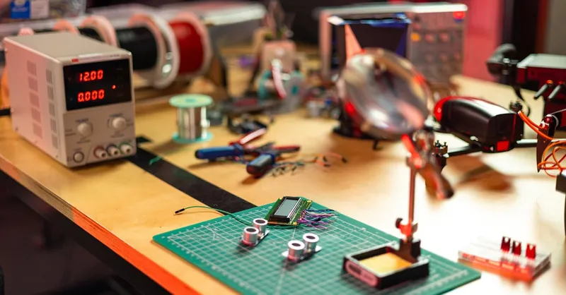
Image courtesy of ThisIsEngineering
Using Serial Console and UART for Low-Level Debugging
When tackling complex hardware issues on Raspberry Pi projects, leveraging the serial console and UART (Universal Asynchronous Receiver-Transmitter) interface is an indispensable low-level debugging technique. The serial console provides direct access to boot logs, kernel messages, and system diagnostics that are often hidden from standard output interfaces. This insight is crucial for catching hardware initialization errors, peripheral communication failures, or kernel panics related to device drivers.
Why Use Serial Console and UART for Debugging?
- Early Boot Log Access: Serial console outputs enable you to monitor the Raspberry Pi’s startup sequence in real-time. This allows you to catch early errors such as bootloader failures, kernel module loading issues, or device tree conflicts that prevent proper hardware initialization.
- Kernel and Driver Messages: Many hardware drivers output status reports, warnings, and error messages over UART that may not appear in graphical desktop environments or standard SSH sessions. These logs reveal root causes of peripheral recognition problems or GPIO initialization failures.
- Remote Debugging Capability: Since UART communication is independent of the Raspberry Pi’s network or graphical environment, you can debug devices that fail to reach a usable state or lose network connectivity during boot.
- Minimal Hardware Requirements: Utilizing a simple USB-to-serial adapter connected to the Pi’s UART pins provides a low-cost, high-value debug interface suitable for headless or embedded projects.
Setting Up Serial Console Debugging
To effectively gather critical boot messages and kernel logs:
- Connect a USB-to-TTL serial adapter to the Raspberry Pi’s UART pins (GPIO14 - TXD, GPIO15 - RXD, and ground).
- Enable the serial console interface by configuring your Pi’s
config.txtand/boot/cmdline.txtfor UART output. - Use terminal software such as
minicom,PuTTY, orscreenon your host PC to listen to the serial port at the default baud rate (usually 115200 baud). - Observe the full boot sequence logs, kernel messages, and any driver initialization output.
Leveraging UART Logs for Hardware Troubleshooting
By analyzing serial console logs, you can:
- Detect bootloader errors, such as corrupted firmware or incompatible SD card images.
- Identify kernel panic stacks caused by faulty hardware or incompatible drivers.
- Pinpoint device initialization failures, like I2C or SPI bus configuration errors.
- Confirm the proper loading of custom device trees or module overlays controlling hardware peripherals.
- Trace power-related warnings embedded in kernel logs indicating undervoltage conditions or regulator failures.
By incorporating serial debugging through UART into your Raspberry Pi troubleshooting toolkit, you gain a powerful, low-level window into system behavior beyond standard software logs. This method enhances your ability to capture elusive hardware faults, accelerates debugging cycles, and ultimately leads to more reliable, responsive hardware designs in your Raspberry Pi and embedded system projects.
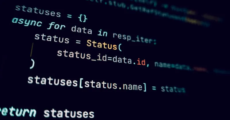
Image courtesy of Stanislav Kondratiev
Detecting and Resolving Interference and Noise Issues
In embedded Raspberry Pi hardware projects, electromagnetic interference (EMI) and electrical noise are common adversaries that can cause erratic sensor readings, communication faults, and system instability. Understanding how interference arises and implementing effective noise mitigation strategies is essential for ensuring reliable hardware operation and accurate data acquisition.
Understanding Electromagnetic Interference and Its Sources
Electromagnetic interference occurs when unwanted electromagnetic signals disrupt the normal operation of electronic circuits. Key sources of EMI in Raspberry Pi projects include:
- Switching power supplies and motors generating high-frequency noise.
- Improperly shielded cables acting as antennas picking up ambient electromagnetic radiation.
- Cross-talk between adjacent signal lines on breadboards or PCBs.
- Ground loops caused by multiple grounding points with different potentials.
EMI can manifest as random data corruption, communication failures on I2C or SPI buses, or sporadic peripheral malfunctions. Being proactive about identifying interference is critical for dependable embedded system performance.
Cable Shielding and Layout Tips to Minimize Noise
Implementing proper cable shielding and thoughtful physical design significantly reduces noise coupling:
- Use shielded cables for sensor lines and communication buses, particularly in electrically noisy environments or longer cable runs. Connect shield grounds appropriately to avoid ground loops.
- Maintain short, direct wiring routes and keep signal cables away from high-current or high-voltage lines to minimize inductive and capacitive coupling.
- Employ twisted pair cables for differential signals or lines sensitive to noise, which cancels out electromagnetic interference effectively.
- Organize wiring harnesses and use ferrite beads or chokes on cables to suppress high-frequency noise.
- On PCBs or custom boards, design ground planes and proper trace separation to reduce interference between signal paths.
Design Strategies to Reduce Noise in Embedded Projects
Beyond physical wiring practices, thoughtful design choices can enhance noise immunity:
- Implement proper ground referencing, ideally a single, low-impedance ground point to prevent ground bounce.
- Apply decoupling capacitors close to power pins of ICs and sensors to smooth voltage fluctuations and filter transient noise.
- Use series termination resistors on data lines to dampen signal reflections and ringing.
- Consider differential signaling protocols or hardware for critical communication buses, enhancing noise rejection.
- Programmatically, implement signal filtering and error checking such as CRC verification or sensor data smoothing algorithms to detect and handle noisy inputs.
By combining these hardware and software noise reduction techniques, Raspberry Pi projects achieve more stable and accurate sensor readings, robust communication, and overall enhanced system reliability. Proactively combating interference at the design and implementation stage prevents frustrating debugging sessions caused by elusive noise-related issues and makes your embedded creations more professional and resilient.
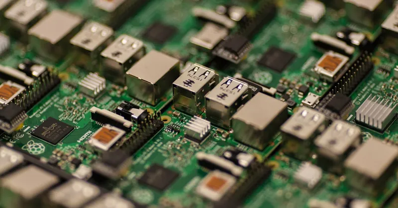
Image courtesy of Craig Dennis
Firmware and Driver Checks Impacting Hardware Functionality
Proper firmware installation, kernel modules, and up-to-date drivers play a pivotal role in ensuring hardware stability and optimal functionality in Raspberry Pi projects. Even well-wired and power-robust setups can exhibit erratic behavior or unrecognized peripherals if the firmware or drivers are missing, outdated, or incompatible. Since Raspberry Pi relies heavily on Linux kernel modules to interface with a diverse array of sensors, displays, and communication devices, maintaining correct software-hardware alignment is essential for seamless operation.
Key Firmware and Driver Considerations
-
Firmware Updates and Compatibility
Raspberry Pi’s firmware controls low-level hardware features ranging from the bootloader to GPU and interfacing protocols. Regularly updating firmware via utilities likerpi-updateor through official Raspberry Pi OS upgrades ensures bug fixes, improved peripheral support, and enhanced power management. Ignoring firmware updates may cause compatibility issues, especially when integrating newer modules or kernel versions. -
Kernel Modules and Device Drivers
The Linux kernel loads specific drivers at boot time or dynamically as hardware is detected. Missing or incompatible kernel modules for peripherals such as cameras, Wi-Fi adapters, or sensor buses can lead to devices not initializing or reporting errors like “device not found.” Use commands likelsmodto list loaded modules anddmesgfor driver-related logs. Installing missing drivers through package managers or compiling custom modules from source might be necessary for specialized hardware. -
Device Tree Overlays
Raspberry Pi uses device tree overlays to enable and configure hardware peripherals without modifying the kernel itself. Incorrect or absent overlays in the/boot/config.txtfile can prevent GPIO pins from being correctly assigned or peripherals from functioning properly. For example, enabling I2C or SPI buses requires corresponding overlays such asi2c-devorspi-dev. Verify these configurations to match your hardware setup precisely. -
Version Mismatch and Dependency Issues
Conflicts often arise when the kernel, firmware, and drivers are updated independently, leading to version mismatches. Ensure all components are updated in a compatible manner—using official repositories or release notes—to avoid instability or peripheral malfunctions.
Best Practices for Firmware and Driver Management
- Regularly update your Raspberry Pi OS and firmware using trusted update mechanisms to maintain synchronization between hardware and software layers.
- Before adding new hardware, consult official documentation or forums to identify required kernel modules or overlays.
- Use diagnostic commands (
lsmod,modprobe,dmesg) to troubleshoot driver loading errors or conflicts. - Consider building custom kernels or modules only when necessary, and test thoroughly in isolated environments to prevent system-wide instability.
Incorporating meticulous firmware and driver verification into your debugging workflow helps not only in stabilizing your Raspberry Pi hardware but also in unlocking advanced features of connected peripherals, ultimately leading to robust and maintainable embedded systems projects.

Image courtesy of Craig Dennis
Preventive Practices and Documentation for Easier Debugging
One of the most effective ways to reduce hardware bugs and speed up Raspberry Pi project debugging is by adopting rigorous preventive practices and maintaining detailed documentation from the outset. Thoughtful preparation not only minimizes the chance of introducing hardware faults but also provides a reliable reference to quickly identify issues when they arise. For complex projects involving multiple sensors, peripherals, and custom circuits, this foresight pays dividends in both development time and project stability.
The Importance of Detailed Project Documentation
Keeping accurate and thorough documentation is a cornerstone of maintainable and debuggable Raspberry Pi hardware projects. This includes:
-
Schematic Diagrams
Clearly drawn circuit schematics capture wiring layouts, power connections, and pin assignments. They serve as a visual blueprint for your hardware setup and dramatically simplify troubleshooting by exposing wiring errors or incompatible connections at a glance. -
Component Specifications and Datasheets
Document the exact components used, including part numbers, voltage requirements, and communication protocols. Having datasheets readily available helps verify compatibility and guides correct handling of signal levels and timing constraints. -
Version Control and Change Logs
Utilize version control systems (e.g., Git) to track changes in both hardware design files (such as PCB layouts or wiring plans) and associated firmware/software code. Maintaining a change log records modifications, allowing you to correlate hardware changes with emerging bugs or failures. -
Configuration and Pin Mapping Tables
Create and update tables listing GPIO pin functions, device addresses (e.g., I2C addresses), and peripheral configurations used in your project. This reduces confusion and prevents conflicts that commonly arise from undocumented or overwritten settings.
Anticipating and Preventing Hardware Bugs Through Planning
Adopting preventive strategies early in the design and build phase helps avoid common pitfalls:
-
Standardize Wiring and Layouts
Consistent color coding for power, ground, data, and control lines reduces wiring mistakes and speeds physical inspections. -
Prototype with Breadboards and Modular Components
Building and testing subsystems independently before final integration isolates hardware issues early, preventing complex interplay of faults. -
Implement Redundancies and Test Points
Adding accessible test points and redundant measurement spots in your circuit facilitates quick voltage and signal checks during debugging. -
Review and Validate Power Requirements
Calculating expected current draws and ensuring power supply headroom avoids undervoltage scenarios that cause intermittent failures.
By embedding these preventive practices and meticulous documentation into your Raspberry Pi hardware workflow, you create a robust foundation that not only streamlines debugging but also enhances collaboration and scalability of projects. This disciplined approach transforms what often feels like a chaotic trial-and-error process into a clear, repeatable methodology—empowering you to build complex, reliable embedded systems with confidence.
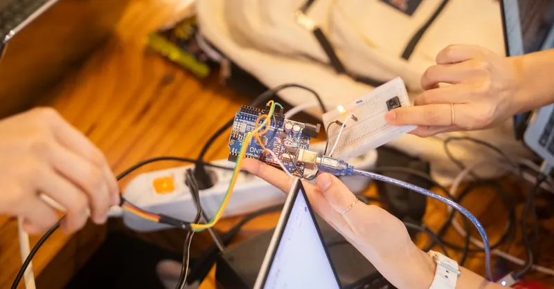
Image courtesy of Youn Seung Jin
Resources and Advanced Techniques for Continuous Learning
Mastering Raspberry Pi hardware debugging is an ongoing journey that benefits immensely from engaging with the vibrant online community, leveraging official documentation, and utilizing advanced diagnostic scripts. These resources and techniques empower you to deepen your understanding, stay updated on best practices, and efficiently tackle complex hardware problems beyond the basics.
Online Communities and Forums for Collaborative Support
Active participation in dedicated Raspberry Pi and embedded systems forums allows you to exchange troubleshooting tips, share project experiences, and gain insights from seasoned developers. Some of the most valuable online communities include:
-
Raspberry Pi Forums (https://www.raspberrypi.org/forums/)
The official forum hosts discussions on hardware issues, peripheral compatibility, and software-hardware integration challenges directly related to Raspberry Pi models and projects. -
Stack Exchange Electrical Engineering & Raspberry Pi Subforums (https://raspberrypi.stackexchange.com/)
These Q&A communities provide detailed, peer-reviewed solutions on microcontroller interfacing, hardware debugging techniques, and embedded C/C++ programming. -
Reddit Communities such as r/raspberry_pi and r/embedded
These platforms offer informal yet insightful discussions, real-world project case studies, and announcements about new tools or hardware releases relevant to Raspberry Pi developers. -
GitHub Repositories and Issue Trackers
Exploring open-source projects and their active issue trackers fosters familiarity with common hardware bugs and patches applied by the community, especially for diagnostic tools and device drivers.
Official Documentation and Technical References
Referencing manufacturer and Raspberry Pi Foundation documentation ensures accurate hardware specifications, pinout details, and configuration guides. Key official resources include:
-
Raspberry Pi Hardware Documentation (https://www.raspberrypi.org/documentation/hardware/)
Contains detailed datasheets, GPIO pinouts, and hardware interfacing information. -
Broadcom SoC Datasheets and Technical Reference Manuals
Essential for low-level hardware interaction and understanding the Raspberry Pi’s processor features. -
Linux Kernel Documentation and Device Tree Overlays
Provides insights into driver configurations, peripheral enablement via overlays, and kernel module interactions critical for hardware functionality.
Leveraging Diagnostic Scripts and Automation Tools
To streamline complex hardware troubleshooting tasks, use or develop diagnostic scripts that can automate repetitive checks and gather detailed system hardware statuses:
-
Python and Bash Scripts for GPIO Testing
Automate pin toggling, input reading, and bus scanning (e.g., I2C address sweeps) to quickly verify hardware connections and detect conflicts. -
System Health Monitoring Tools
Utilize scripts integrating commands likevcgencmd,dmesg, andi2cdetectto provide comprehensive reports on power status, peripheral initialization errors, and communication bus health. -
Custom Logging and Alerting Frameworks
Establish automated logging of hardware events and set alerts for undervoltage warnings, device disconnects, or driver failures to proactively address issues before they escalate.
By consistently engaging with these advanced resources and learning techniques, you not only elevate your troubleshooting capabilities but also keep pace with the evolving Raspberry Pi hardware ecosystem. This continuous knowledge enhancement is vital for building resilient, high-performance embedded systems and pushing the creative boundaries of your projects.
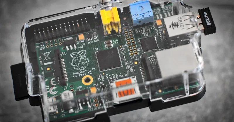
Image courtesy of Pixabay