GPIO Programming Tutorial for Raspberry Pi and Arduino
Category: Embedded Systems
Master GPIO Programming on Raspberry Pi and Arduino
If you're diving into the world of electronics and embedded systems, understanding GPIO (General Purpose Input/Output) programming is essential for building interactive projects on Raspberry Pi and Arduino. Whether you're a hobbyist eager to bring sensors, LEDs, and motors to life or an embedded systems developer looking to refine your programming skills, mastering GPIO pin control bridges your software with the physical world. You’re here because you want a clear, practical guide that doesn’t overwhelm with jargon but delivers actionable insights in Python, C/C++, and wiring for both platforms. Unlike scattered tutorials, this post offers a cohesive, side-by-side approach to GPIO programming fundamentals, setup, and real project examples tailored for microcontroller enthusiasts across skill levels. By the end, you'll confidently control devices and understand the nuances between Raspberry Pi’s Linux-based GPIO and Arduino’s microcontroller-centric GPIO, setting you up to create smarter, more responsive electronics projects. Ready to open the door to embedded creativity? Let’s get started!
- Master GPIO Programming on Raspberry Pi and Arduino
- Overview of GPIO: What Are GPIO Pins and How Do Raspberry Pi and Arduino Differ?
- Setting Up Your Hardware: Connecting Raspberry Pi and Arduino GPIO Safely
- Configuring the Software Environment
- Basic GPIO Control: Reading Button Input and Controlling an LED
- Understanding GPIO Modes and Pull-Up/Pull-Down Resistors
- Advanced GPIO Features: PWM and Interrupts on Raspberry Pi and Arduino
- Troubleshooting Common GPIO Issues: Checklist and Solutions
- Hands-On Project Example: Build an Interactive Sensor-Actuator System on Raspberry Pi and Arduino
- Best Practices and Optimization Tips for Efficient GPIO Programming
- Resources and Next Steps: Deepen Your GPIO and Embedded Systems Expertise
Overview of GPIO: What Are GPIO Pins and How Do Raspberry Pi and Arduino Differ?
GPIO (General Purpose Input/Output) pins are the essential interface between a microcontroller or microprocessor and the external world, enabling your Raspberry Pi or Arduino to read sensor inputs or control devices like LEDs, motors, and displays. These pins can be programmed to act as either inputs (to receive signals) or outputs (to send signals), making them fundamental for interactive embedded systems and DIY electronics projects.
GPIO on Raspberry Pi vs. Arduino: Key Hardware Differences
While both platforms offer GPIO functionality, the way they handle these pins at the hardware level differs significantly:
- Raspberry Pi GPIO:
- The Raspberry Pi uses a Broadcom ARM-based processor running a full Linux operating system.
- Its GPIO pins are part of a multi-purpose pin header that supports various protocols including UART, SPI, I2C, PWM, and plain digital I/O.
- These pins operate at 3.3V logic levels, which means toggling a pin HIGH sets it to 3.3 volts. Applying voltages above 3.3V risks damaging the Pi.
- GPIO control is abstracted through the Linux kernel, requiring software libraries like RPi.GPIO or pigpio to interact with pins safely and efficiently.
-
Because it’s running an OS, GPIO timings can be less deterministic compared to microcontrollers.
-
Arduino GPIO:
- Arduino boards utilize microcontrollers (e.g., the ATmega328 on the Uno) that run bare-metal code without an operating system, allowing for precise timing control and real-time performance.
- GPIO pins on Arduino are true digital input/output pins that operate mostly at 5V logic levels (some newer boards use 3.3V).
- Pins can be individually programmed as input, output, or analog input (on analog-capable pins).
- Direct register manipulation is possible to maximize performance in C/C++.
- Power constraints and pin functionalities vary slightly between Arduino models but generally follow a consistent and simpler hardware design tailored for embedded applications.
Understanding these differences is crucial before diving into coding GPIOs on either platform, as the voltage levels, pin capabilities, and programming approaches dictate the proper hardware connections and software routines you should employ. In the following sections, we'll break down how to set up and program GPIO pins on Raspberry Pi and Arduino using their respective best practices and languages.
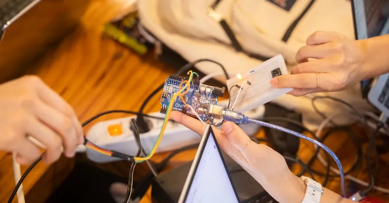
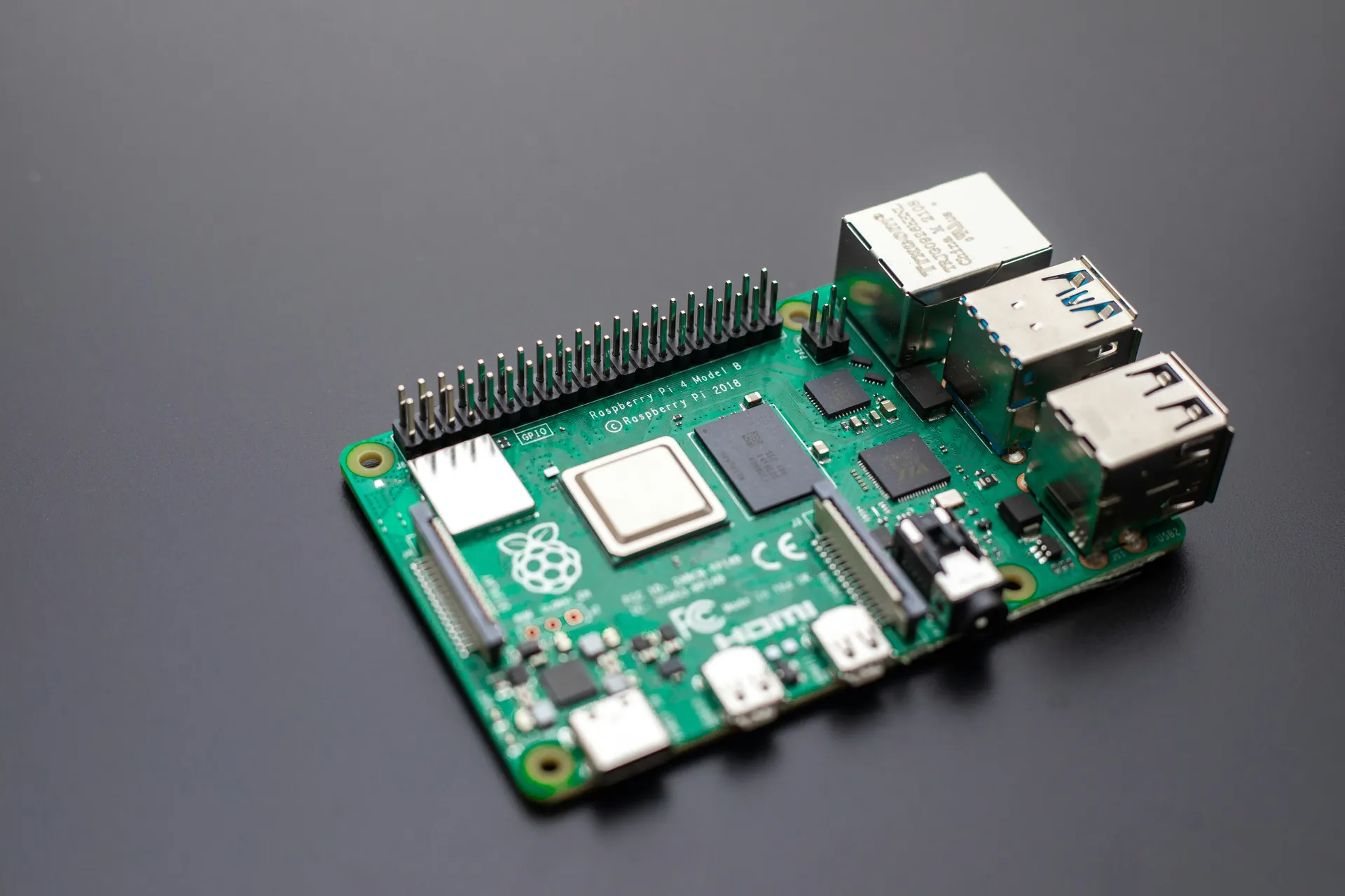
Image courtesy of Youn Seung Jin
Setting Up Your Hardware: Connecting Raspberry Pi and Arduino GPIO Safely
Before you dive into GPIO programming, the foundation of any successful Raspberry Pi or Arduino project is a well-planned hardware setup. Correctly connecting your boards and external components ensures reliable operation and protects your devices from damage. This section guides you through critical considerations including power supply, pinout references, and essential safety tips for interfacing GPIO pins with sensors, actuators, and other peripherals.
Power Considerations: Protect Your Boards and Circuits
A stable and appropriate power supply is paramount. Both Raspberry Pi and Arduino have specific voltage requirements for their GPIO pins:
-
Raspberry Pi operates at 3.3V logic levels on its GPIO pins. Never apply voltages exceeding 3.3V directly to these pins as it can cause permanent damage to the Broadcom processor. When connecting 5V sensors or modules, use logic level shifters or voltage dividers to adapt voltage levels safely.
-
Arduino Uno and many classic boards use 5V logic levels, though some newer models or variants operate at 3.3V. Ensure that any connected peripherals match the Arduino’s voltage standard or include appropriate level shifting.
Additionally, power your boards using recommended power supplies (e.g., 5V 2.5A for Raspberry Pi 3/4 and regulated 7-12V input for Arduino’s barrel jack or USB power). Avoid powering external components directly from GPIO pins as their output current limits are low (typically around 16-20mA per pin). Use separate power sources or regulated power rails for high-current devices like motors or large arrays of LEDs.
Pinout References: Know Your Pins Before You Connect
Familiarize yourself with the GPIO pin mapping of your platform to avoid wiring errors:
-
The Raspberry Pi 40-pin header includes multiple GPIO pins alongside power (3.3V, 5V) and ground (GND) pins. Use official Raspberry Pi pinout diagrams or online interactive tools like Pinout.xyz to correctly identify pins supporting digital I/O, PWM, I2C, SPI, and UART.
-
The Arduino Uno 28-pin DIP features digital I/O pins numbered D0 through D13 plus six analog input pins A0-A5. Each pin’s capabilities, such as PWM output or external interrupts, are clearly documented in the Arduino reference.
Always label your wires and double-check connections before powering the board to prevent shorts.
Safety Tips for Interfacing External Components
Interfacing external components with GPIO pins demands caution to avoid damage both to the board and to connected devices:
- Use current-limiting resistors with LEDs (usually 220Ω to 330Ω) to prevent excessive current draw.
- For mechanical switches and buttons, implement pull-up or pull-down resistors to stabilize input readings and avoid floating inputs.
- When working with motors, relays, or other inductive loads, include flyback diodes and external driver circuits to protect your pins from voltage spikes.
- Never connect GPIO pins directly to high-voltage sources or AC mains.
- Use a multimeter to verify voltage levels and continuity before powering the circuit.
- Consider integrating breadboards and jumper wires for prototyping to reduce soldering errors and allow easy modifications.
By attentively planning your hardware connections, respecting voltage and current limits, and applying these safety practices, you'll create a solid, damage-resistant starting point for GPIO programming with Raspberry Pi and Arduino — unlocking your project’s true potential with confidence and reliability.

Image courtesy of Mathias Wouters
Configuring the Software Environment
Before you start controlling GPIO pins on your Raspberry Pi and Arduino, it’s crucial to properly set up the software environment. This ensures seamless development and reliable communication between your code and hardware. Below, we walk through setting up Python on Raspberry Pi and installing the Arduino IDE on your computer, along with installing key libraries like RPi.GPIO for Raspberry Pi and core support packages for Arduino. Having these tools ready enables you to write, compile, and upload GPIO control programs efficiently.
Setting Up Python and GPIO Libraries on Raspberry Pi
Raspberry Pi runs a full Linux operating system, making Python the most popular and accessible language for GPIO programming. To configure Python for GPIO control:
-
Ensure Python is Installed:
Most Raspberry Pi OS installations come with Python pre-installed. Verify by running:
bash
   python3 --version
or
bash
   python --version
If Python is missing, install it with:
bash sudo apt-get update sudo apt-get install python3 -
Install RPi.GPIO Library:
The RPi.GPIO library provides a simple API to interact with the Pi's GPIO pins. Install it using:
bash
   sudo apt-get install python3-rpi.gpio
Alternatively, usepip3for the latest version:
bash pip3 install RPi.GPIO -
Verify Installation:
Test your installation by running a quick Python script:
python
   import RPi.GPIO as GPIO
   GPIO.setmode(GPIO.BCM)
   print("RPi.GPIO is ready!")
Successful execution confirms your environment is ready for GPIO programming.
Optional Libraries: Depending on project complexity, consider installing libraries like gpiozero for simplified GPIO access or pigpio for advanced timing control.
Installing Arduino IDE and Core Support
For Arduino GPIO programming, the Arduino IDE is the official development environment, providing an easy way to write, compile, and upload code using C/C++.
-
Download and Install Arduino IDE:
Visit the official Arduino website and download the latest version compatible with your OS (Windows, macOS, or Linux). Follow installation instructions to complete setup. -
Set Up Your Arduino Board:
Connect your Arduino to the computer via USB. Open the Arduino IDE, and select the appropriate board and port from the Tools menu: - Navigate to Tools > Board and select your Arduino model (e.g., Arduino Uno).
-
Go to Tools > Port and select the corresponding COM port.
-
Install Additional Core Support or Libraries:
- For different Arduino boards or third-party hardware, you may need to add additional board definitions via the Boards Manager found under Tools > Board > Boards Manager.
-
Install necessary libraries to manage sensors, actuators, or specific modules through Sketch > Include Library > Manage Libraries.
-
Test Arduino Setup:
Upload the classic Blink example sketch from File > Examples > 01.Basics > Blink to verify everything is working correctly.
By following these steps to configure your software environment, you establish a strong foundation for GPIO programming that harnesses the full capabilities of both Raspberry Pi and Arduino platforms. Proper installation of these essential tools and libraries optimizes development workflow, enabling you to build robust projects that interact confidently with hardware components.

Image courtesy of cottonbro studio
Basic GPIO Control: Reading Button Input and Controlling an LED
Mastering simple GPIO tasks like reading a button press and toggling an LED lays the foundation for more advanced Raspberry Pi and Arduino projects. This section demonstrates straightforward examples of configuring input and output pins on both platforms, showcasing Python code for Raspberry Pi and C/C++ code for Arduino. By the end, you'll understand how to detect button states and drive LEDs with minimal hardware and software complexity.
Reading a Button and Controlling an LED on Raspberry Pi Using Python
On the Raspberry Pi, you typically use the RPi.GPIO library or gpiozero for GPIO interaction. Below is a basic example using RPi.GPIO to read a push-button input and control an LED output:
import RPi.GPIO as GPIO
import time

# Set GPIO mode to BCM numbering
GPIO.setmode(GPIO.BCM)

# Define GPIO pins
BUTTON_PIN = 18  # Button connected to GPIO18
LED_PIN = 23     # LED connected to GPIO23

# Setup pins
GPIO.setup(BUTTON_PIN, GPIO.IN, pull_up_down=GPIO.PUD_UP)  # Enable internal pull-up resistor
GPIO.setup(LED_PIN, GPIO.OUT)  # Set LED pin as output

try:
    while True:
        button_state = GPIO.input(BUTTON_PIN)
        if button_state == GPIO.LOW:  # Button pressed (assuming active low)
            GPIO.output(LED_PIN, GPIO.HIGH)  # Turn LED on
        else:
            GPIO.output(LED_PIN, GPIO.LOW)   # Turn LED off
        time.sleep(0.1)  # Debounce delay
except KeyboardInterrupt:
    pass
finally:
    GPIO.cleanup()  # Reset GPIO settings
Key points:
- The button is connected with an internal pull-up resistor to avoid floating input signals.
- Reading
GPIO.LOWmeans the button is pressed (active low wiring). - The LED toggles correspondingly, demonstrating output control.
GPIO.cleanup()ensures safe pin release when the program ends.
This example runs on Linux OS with Python and RPi.GPIO installed, making it ideal for beginners wanting quick feedback from hardware without complex setup.
Equivalent GPIO Control on Arduino Using C/C++
Arduino programs, or "sketches," leverage C/C++ syntax and run directly on the microcontroller. The following example reads a push-button connected to a digital input pin and controls an LED on another pin:
const int buttonPin = 2;  // Button connected to digital pin 2
const int ledPin = 13;    // Built-in LED on most Arduino boards

void setup() {
  pinMode(buttonPin, INPUT_PULLUP);  // Configure button pin with internal pull-up resistor
  pinMode(ledPin, OUTPUT);            // Set LED pin as output
}

void loop() {
  int buttonState = digitalRead(buttonPin);

  if (buttonState == LOW) {  // Button pressed (active low)
    digitalWrite(ledPin, HIGH);  // Turn LED on
  } else {
    digitalWrite(ledPin, LOW);   // Turn LED off
  }
}
Highlights:
INPUT_PULLUPactivates Arduino’s internal pull-up resistor, simplifying the wiring of the button.- The button press condition checks for
LOWdue to the active low configuration. - The built-in LED on pin 13 is a convenient output for testing without external hardware.
- The loop runs continuously, instantly responding to button state changes.
Tips for Reliable GPIO Input and Output Control
Whether programming Raspberry Pi in Python or Arduino in C/C++, following these best practices will enhance your GPIO control reliability:
- Use internal pull-up or pull-down resistors to stabilize input readings and avoid floating pins.
- Prefer active low wiring for buttons and switches because it simplifies software logic with pull-ups.
- Include debounce mechanisms in hardware (capacitors) or software (delays or state-change detection) to prevent erroneous multiple readings.
- Always initialize GPIO pins explicitly as inputs or outputs before use.
- When controlling LEDs, use current-limiting resistors (220Ω to 330Ω) to extend component lifespan and prevent board damage.
This hands-on GPIO example is perfect for beginning embedded developers and hobbyists. It bridges the abstractions of Python scripting on Linux with the direct hardware control of C/C++ on microcontrollers, enabling you to create responsive physical interfaces with minimal effort across Raspberry Pi and Arduino platforms.
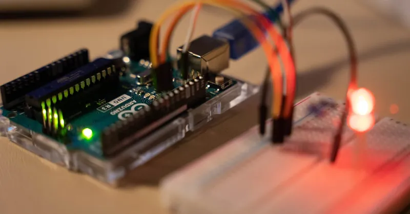
Image courtesy of Chengxin Zhao
Understanding GPIO Modes and Pull-Up/Pull-Down Resistors
When programming GPIO pins on Raspberry Pi and Arduino, one of the fundamental concepts you must grasp is the GPIO pin mode — whether a pin acts as an input or output — and how pull-up and pull-down resistors affect signal stability. Proper configuration of these modes and resistors ensures accurate readings from sensors and reliable control of actuators, preventing erratic behavior caused by floating inputs.
GPIO Modes: Input and Output Explained
Each GPIO pin can be configured in one of two basic modes:
- Input Mode: The pin reads external signals like button presses, sensor data, or other digital devices.
- Output Mode: The pin sends signals to devices such as LEDs, motors, or relays by setting the pin HIGH or LOW.
Choosing the correct mode is essential; for instance, attempting to read a value from a pin set as output can return incorrect or no data. Conversely, writing to a pin configured as input has no effect on the pin's voltage level.
The Role of Pull-Up and Pull-Down Resistors
Digital inputs can sometimes be left "floating" when no electrical connection is made, meaning their readings fluctuate unpredictably between HIGH and LOW. This interference leads to unstable inputs and faulty program behavior. Pull-up and pull-down resistors solve this by establishing a default voltage level on the input pin:
- Pull-Up Resistor: Connects the input pin to a high voltage level (3.3V on Raspberry Pi, 5V on Arduino), ensuring the pin reads HIGH when the switch is open.
- Pull-Down Resistor: Connects the input pin to ground (GND), ensuring the pin reads LOW when the switch is open.
Using pull resistors guarantees that your input pins have a defined logic level at all times, removing ambiguity and enhancing input reliability.
Internal vs. External Pull Resistors
Both Raspberry Pi and Arduino provide internal pull-up resistors that can be enabled via software, eliminating the need for external components in many cases:
-
Raspberry Pi: Using libraries like RPi.GPIO, internal pull-up or pull-down resistors can be enabled by setting the
pull_up_downparameter inGPIO.setup().
For example:python GPIO.setup(18, GPIO.IN, pull_up_down=GPIO.PUD_UP) # Enable internal pull-up resistor on GPIO18Raspberry Pi supports both internal pull-up and pull-down resistors. -
Arduino: The Arduino microcontroller supports internal pull-up resistors accessible via the
INPUT_PULLUPmode, but it does not have internal pull-down resistors.
For example:cpp pinMode(2, INPUT_PULLUP); // Activate internal pull-up resistor on pin 2If you require a pull-down resistor on Arduino, you must add an external resistor (typically 10kΩ) connected between the pin and GND.
Practical Importance and Code Examples
Failing to use pull-up or pull-down resistors often results in floating inputs, where the pin voltage shifts due to electromagnetic interference, causing the microcontroller to misinterpret the signal. This is especially common with buttons and switches.
Below are brief examples highlighting the use of internal pull-up resistors on Raspberry Pi and Arduino to read button presses cleanly and reliably:
Raspberry Pi Python Example:
import RPi.GPIO as GPIO

GPIO.setmode(GPIO.BCM)
GPIO.setup(17, GPIO.IN, pull_up_down=GPIO.PUD_UP)  # Internal pull-up enabled

if GPIO.input(17) == GPIO.LOW:
    print("Button Pressed")
Arduino C++ Example:
void setup() {
  pinMode(3, INPUT_PULLUP);  // Internal pull-up enabled
  Serial.begin(9600);
}

void loop() {
  if (digitalRead(3) == LOW) {
    Serial.println("Button Pressed");
  }
}
By understanding and properly configuring GPIO modes along with internal or external pull-up/pull-down resistors, you ensure your Raspberry Pi and Arduino projects operate with stable, accurate inputs and dependable outputs. This critical knowledge improves the robustness of sensor readings, switch controls, and overall embedded system behavior, streamlining your journey into GPIO programming.

Image courtesy of Mathias Wouters
Advanced GPIO Features: PWM and Interrupts on Raspberry Pi and Arduino
Once you're comfortable with basic GPIO input/output control, it’s time to explore advanced GPIO features that unlock greater precision and responsiveness in your projects. Two key functionalities that both Raspberry Pi and Arduino support are Pulse Width Modulation (PWM) and interrupts. Leveraging these features enables you to perform smooth LED dimming, motor speed control, and immediate reactions to external events—critical for sophisticated embedded systems and interactive designs.
Pulse Width Modulation (PWM): Flicker-Free LED Dimming and Motor Speed Control
PWM is a powerful technique that simulates variable voltage levels by switching a digital pin ON and OFF rapidly at a specific frequency, adjusting the ratio of ON time (duty cycle) to OFF time. This modulation changes the effective power delivered without analog hardware, allowing for:
- Smooth LED brightness adjustment: By varying the PWM duty cycle, LEDs can fade from off to full brightness.
- Motor speed regulation: PWM controls how much power the motor receives, enabling fine-tuned speed control.
- Servo positioning: Specialized PWM signals guide servo motors to precise angles.
PWM on Raspberry Pi
On Raspberry Pi, hardware PWM is limited to few pins, but software PWM libraries like RPi.GPIO or pigpio provide flexible and easy-to-use PWM control on multiple pins.
Example using RPi.GPIO in Python to dim an LED:
import RPi.GPIO as GPIO
import time

LED_PIN = 18
GPIO.setmode(GPIO.BCM)
GPIO.setup(LED_PIN, GPIO.OUT)

pwm = GPIO.PWM(LED_PIN, 1000)  # Initialize PWM on 1 kHz frequency
pwm.start(0)  # Start with 0% duty cycle (LED off)

try:
    while True:
        for duty_cycle in range(0, 101, 5):  # Fade in
            pwm.ChangeDutyCycle(duty_cycle)
            time.sleep(0.05)
        for duty_cycle in range(100, -1, -5):  # Fade out
            pwm.ChangeDutyCycle(duty_cycle)
            time.sleep(0.05)
except KeyboardInterrupt:
    pass
finally:
    pwm.stop()
    GPIO.cleanup()
PWM on Arduino
Arduino boards feature built-in analogWrite() PWM support on predefined pins, allowing straightforward motor speed or LED brightness control.
Example in Arduino C++ to fade an LED using PWM:
const int ledPin = 9;  // PWM-capable pin

void setup() {
  pinMode(ledPin, OUTPUT);
}

void loop() {
  for (int brightness = 0; brightness <= 255; brightness += 5) {
    analogWrite(ledPin, brightness);  // Increase brightness
    delay(30);
  }
  for (int brightness = 255; brightness >= 0; brightness -= 5) {
    analogWrite(ledPin, brightness);  // Decrease brightness
    delay(30);
  }
}
Interrupts: Responsive Input Handling for Real-Time Events
Interrupts enable your microcontroller or processor to respond immediately to external events—like button presses or sensor triggers—without needing to constantly poll inputs, improving responsiveness and CPU efficiency.
- Interrupts pause the main program flow to execute a dedicated Interrupt Service Routine (ISR).
- ISRs execute quickly to handle critical tasks such as reading inputs or setting flags.
- After ISR completion, the program resumes normally.
Interrupts on Raspberry Pi
Due to its Linux-based OS, Raspberry Pi supports edge detection callbacks via libraries like RPi.GPIO or gpiozero rather than low-level hardware interrupts.
Example: Detecting a button press using RPi.GPIO interrupts in Python:
import RPi.GPIO as GPIO
import time

BUTTON_PIN = 17
LED_PIN = 27

GPIO.setmode(GPIO.BCM)
GPIO.setup(BUTTON_PIN, GPIO.IN, pull_up_down=GPIO.PUD_UP)
GPIO.setup(LED_PIN, GPIO.OUT)
GPIO.output(LED_PIN, GPIO.LOW)

def button_callback(channel):
    # Toggle LED on button press event
    current_state = GPIO.input(LED_PIN)
    GPIO.output(LED_PIN, not current_state)
    print("Button pressed! LED toggled.")

GPIO.add_event_detect(BUTTON_PIN, GPIO.FALLING, callback=button_callback, bouncetime=200)

try:
    while True:
        time.sleep(1)  # Main loop can do other tasks
except KeyboardInterrupt:
    pass
finally:
    GPIO.cleanup()
Interrupts on Arduino
Arduino supports hardware interrupts on certain pins, allowing ISRs for extremely fast, real-time handling.
Example: Using an interrupt to toggle an LED on button press (pin 2 triggers interrupt):
const int ledPin = 13;
const int buttonInterruptPin = 2;
volatile bool ledState = false;

void setup() {
  pinMode(ledPin, OUTPUT);
  pinMode(buttonInterruptPin, INPUT_PULLUP);
  attachInterrupt(digitalPinToInterrupt(buttonInterruptPin), toggleLED, FALLING);
}

void loop() {
  digitalWrite(ledPin, ledState);
}

void toggleLED() {
  ledState = !ledState;  // Toggle LED state
}
Key Considerations for PWM and Interrupts
- PWM frequency and resolution: Choose PWM frequencies appropriate for your device; for LEDs, ~1kHz is common, while motors might require different rates.
- Interrupt safety: Keep ISRs short and avoid using functions like
delay()inside them. Use volatile variables to share data between ISR and main code. - Debouncing inputs: When using interrupts with mechanical buttons, use software or hardware debounce to prevent multiple triggers.
- Platform limitations: Raspberry Pi’s software-based interrupts are less deterministic than microcontroller ISRs due to OS multitasking.
By mastering PWM for precise signal control and interrupt-driven input handling, you can elevate your Raspberry Pi and Arduino projects to professional-grade embedded systems capable of smooth control and instant responsiveness, broadening your creative possibilities in automation, robotics, and interactive electronics.

Image courtesy of Thirdman
Troubleshooting Common GPIO Issues: Checklist and Solutions
Working with GPIO pins on Raspberry Pi and Arduino opens up countless creative possibilities, but it's not uncommon to encounter common issues that can halt your project progress. Being aware of frequent pitfalls in GPIO programming and hardware setup—and knowing how to resolve them—ensures smoother development and more reliable outcomes. Below is a comprehensive troubleshooting checklist focusing on the top hurdles including incorrect pin numbering, voltage mismatches, and missing library dependencies.
1. Incorrect Pin Numbering or Wiring
- Mismatch between physical pin numbering and software GPIO numbering: Raspberry Pi offers two main numbering schemes—BCM (Broadcom SOC channel) and BOARD (physical pin numbers). Confusing these will cause your code to manipulate the wrong pins, resulting in no response or erratic behavior.
-
Solution: Always specify and consistently use one numbering scheme. For Raspberry Pi, BCM mode is preferred for flexibility and clarity (
GPIO.setmode(GPIO.BCM)in Python). -
Arduino pin confusion: Arduino pins are generally numbered as digital pins (D0-D13) and analog pins (A0-A5), but mixing analog pin names or misunderstanding PWM-capable pins can cause issues when controlling outputs like LEDs or motors.
-
Solution: Consult the Arduino board pinout and confirm if a pin supports your required function (digital I/O, PWM, interrupts).
-
Loose or wrong wiring on breadboards and connectors: This is a hardware classic. Incorrect jumper wire placement or poor contact on breadboards leads to intermittent or no signal.
- Solution: Double-check wiring according to pinout diagrams. Use a multimeter to verify connectivity and voltages before running your program.
2. Voltage Level Mismatches and Current Overload
- Applying 5V signals directly to Raspberry Pi GPIO pins: Raspberry Pi GPIOs are 3.3V tolerant only. Feeding 5V signals can damage the Pi permanently.
-
Solution: Use level shifters or voltage dividers when interfacing 5V sensors or modules.
-
Drawing too much current from GPIO pins: Each pin can source or sink only a limited current (e.g., ~16mA on Raspberry Pi, 20mA on Arduino pins). Connecting LEDs without current-limiting resistors or driving motors directly can overload pins.
-
Solution: Always include appropriate resistors with LEDs and use driver circuits (transistors, motor driver boards) for high-current loads.
-
Power supply issues affecting GPIO behavior: Insufficient or unstable power can cause unexpected GPIO output levels or rebooting boards under load.
- Solution: Provide proper, regulated power supplies respecting your board’s specs and separate high-current peripherals from GPIO lines.
3. Missing or Improper Library Installation and Usage
- RPi.GPIO or other GPIO libraries not installed or outdated on Raspberry Pi: Attempting to run GPIO scripts without required libraries leads to import errors or runtime exceptions.
-
Solution: Ensure libraries like
RPi.GPIOorgpiozeroare correctly installed and updated (sudo apt-get install python3-rpi.gpioorpip3 install RPi.GPIO). -
Wrong setup or missing Arduino core libraries: Without installing the Arduino IDE or configuring the correct board and port settings, your code cannot be uploaded or will fail during compilation.
-
Solution: Verify that the Arduino IDE is installed, board selection matches your hardware, and USB drivers are functioning properly.
-
Using incompatible functions across platforms: For example, Arduino code relying on
digitalWrite()and Raspberry Pi code needing library-specific GPIO functions must not be interchanged. - Solution: Always write and test platform-specific GPIO code and dependencies.
4. Pin Mode and Pull-Up/Down Resistor Misconfiguration
- GPIO pins configured incorrectly as input instead of output or vice versa: This mistake leads to unresponsive pins or inability to read inputs properly.
-
Solution: Explicitly set pin modes in your code before use (
GPIO.setup(pin, GPIO.OUT)on Pi,pinMode(pin, OUTPUT)on Arduino). -
Floating inputs without pull-up or pull-down resistors: Unstable or fluctuating input signals caused by floating pins are a frequent headache with buttons or sensors.
- Solution: Use internal pull-up/down resistors where available, or add external resistors (10kΩ) for stable inputs.
5. Software Permissions and OS-Related Issues (Raspberry Pi)
- Running GPIO scripts without proper permissions: Raspberry Pi requires root privileges to access GPIO pins through libraries like RPi.GPIO.
-
Solution: Run scripts with
sudoor configure user groups appropriately to grant GPIO access. -
Conflicts with other system services controlling GPIO pins: Some processes or services (e.g., device tree overlays or hardware watchdogs) may block GPIO pins unexpectedly.
- Solution: Check for and disable interfering services, or reserve pins explicitly where possible.
By systematically checking each of these areas during development, you can quickly diagnose and fix common GPIO issues that derail Raspberry Pi and Arduino projects. This proactive troubleshooting mindset not only saves time but also protects your hardware investments, empowering you to build robust, creative embedded systems with confidence.
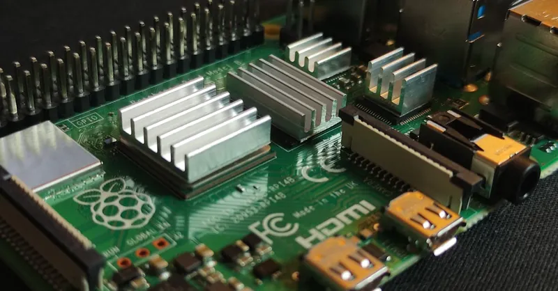
Image courtesy of Mathias Wouters
Hands-On Project Example: Build an Interactive Sensor-Actuator System on Raspberry Pi and Arduino
To solidify your learnings on GPIO programming, let’s dive into a practical project that combines sensors and actuators on both Raspberry Pi and Arduino platforms. This interactive example involves reading data from a temperature sensor and controlling an LED and a buzzer as actuators, providing real-time physical feedback. By building this project, you'll reinforce your understanding of GPIO input/output handling, analog-digital interfacing, and basic control logic with clear, step-by-step instructions tailored for both Raspberry Pi (using Python) and Arduino (using C/C++). This hands-on experience bridges theory and application, empowering you to integrate diverse components creatively.
Project Overview
In this project, you will:
- Connect a temperature sensor (e.g., TMP36 or LM35) to read ambient temperature values through an analog input (Arduino) or an ADC module for Raspberry Pi.
- Use conditional logic to:
- Turn on a green LED when temperature is within a safe range.
- Activate a red LED and buzzer when temperature exceeds a predefined threshold, signaling a warning.
- Implement efficient GPIO pin configuration, sensor reading, and actuator control aligned with best practices learned earlier.
Step-by-Step Instructions
Hardware Components Needed
- Raspberry Pi (any model with GPIO pins)
- Arduino Uno (or compatible board)
- TMP36 or LM35 Temperature Sensor
- Green LED with 220Ω resistor
- Red LED with 220Ω resistor
- Piezo buzzer
- Breadboard and jumper wires
- (For Raspberry Pi) MCP3008 ADC chip or similar to read analog sensor values
Raspberry Pi Setup and Code Highlights
Because Raspberry Pi lacks native analog input, use an MCP3008 ADC to interface the temperature sensor. Connect the MCP3008 via SPI and use the spidev Python library to read sensor values.
- Wiring:
- Connect the temperature sensor output to one ADC channel.
-
Connect LEDs and buzzer to separate GPIO output pins with appropriate current-limiting resistors.
-
Python Script Overview:
import spidev
import RPi.GPIO as GPIO
import time

# GPIO pins
GREEN_LED = 17
RED_LED = 27
BUZZER = 22

# Setup GPIO
GPIO.setmode(GPIO.BCM)
GPIO.setup([GREEN_LED, RED_LED, BUZZER], GPIO.OUT, initial=GPIO.LOW)

# Initialize SPI for MCP3008
spi = spidev.SpiDev()
spi.open(0, 0)  # SPI bus 0, device 0

def read_adc(channel=0):
    adc = spi.xfer2([1, (8 + channel) << 4, 0])
    data = ((adc[1] & 3) << 8) + adc[2]
    return data

def get_temperature_c(adc_value):
    voltage = (adc_value * 3.3) / 1023  # Assuming 3.3V reference
    temp_c = (voltage - 0.5) * 100  # TMP36 formula
    return temp_c

try:
    while True:
        adc_value = read_adc()
        temp_c = get_temperature_c(adc_value)

        if temp_c < 30:
            GPIO.output(GREEN_LED, GPIO.HIGH)
            GPIO.output(RED_LED, GPIO.LOW)
            GPIO.output(BUZZER, GPIO.LOW)
        else:
            GPIO.output(GREEN_LED, GPIO.LOW)
            GPIO.output(RED_LED, GPIO.HIGH)
            GPIO.output(BUZZER, GPIO.HIGH)

        print(f"Temperature: {temp_c:.1f}°C")
        time.sleep(1)

except KeyboardInterrupt:
    pass

finally:
    GPIO.cleanup()
    spi.close()
Arduino Setup and Code Highlights
Arduino’s analog pins can directly read the temperature sensor output, simplifying hardware connection.
- Wiring:
- Connect the temperature sensor output to analog input pin A0.
- Connect green LED and red LED to digital output pins (with resistors).
-
Connect buzzer to a digital pin capable of driving a small load.
-
Arduino Sketch Overview:
const int tempSensorPin = A0;
const int greenLedPin = 9;
const int redLedPin = 10;
const int buzzerPin = 11;

void setup() {
  pinMode(greenLedPin, OUTPUT);
  pinMode(redLedPin, OUTPUT);
  pinMode(buzzerPin, OUTPUT);
  Serial.begin(9600);
}

float readTemperatureC() {
  int sensorValue = analogRead(tempSensorPin);
  float voltage = sensorValue * (5.0 / 1023.0);
  float tempC = (voltage - 0.5) * 100;
  return tempC;
}

void loop() {
  float temperature = readTemperatureC();
  Serial.print("Temperature: ");
  Serial.print(temperature);
  Serial.println(" °C");

  if (temperature < 30.0) {
    digitalWrite(greenLedPin, HIGH);
    digitalWrite(redLedPin, LOW);
    digitalWrite(buzzerPin, LOW);
  } else {
    digitalWrite(greenLedPin, LOW);
    digitalWrite(redLedPin, HIGH);
    digitalWrite(buzzerPin, HIGH);
  }
  delay(1000);
}
Benefits of this Project for GPIO Learning
- Multi-pin control: You practice managing multiple GPIO pins simultaneously, configuring inputs and outputs correctly.
- Analog-to-digital interfacing: Integrate analog sensors with microcontrollers and handle the Raspberry Pi workaround using ADC.
- Conditional logic: Develop real-time decision-making embedded in software based on sensor data.
- Cross-platform knowledge: Gain parallel insights into Raspberry Pi’s Linux-based GPIO handling in Python and Arduino’s embedded C++ coding environment.
- Component integration: Experience wiring sensors and actuators safely with appropriate resistors and hardware setups.
This interactive sensor-actuator project is an ideal next step after mastering basic GPIO concepts, preparing you for more complex embedded system challenges such as data logging, remote monitoring, or IoT integration. Dive in, experiment, and watch your code translate sensor readings into meaningful physical actions!

Image courtesy of Youn Seung Jin
Best Practices and Optimization Tips for Efficient GPIO Programming
Achieving scalable, reliable embedded systems with Raspberry Pi and Arduino goes beyond just toggling GPIO pins—it requires thoughtful design, efficient coding, and mindful hardware management. Implementing best practices and optimization techniques can dramatically enhance your project’s performance, maintainability, and power efficiency, especially when dealing with complex applications or long-term deployments.
Efficient GPIO Usage
-
Minimize Active Pin States
Keep only the necessary GPIO pins active at any time. Unused pins should be configured as inputs with internal pull-up or pull-down resistors enabled to prevent floating states and reduce potential noise. -
Use Hardware PWM and Dedicated Features
Whenever possible, utilize hardware-supported PWM channels and interrupts instead of software timers for tasks requiring precise timing or fast response. This reduces CPU load and improves timing accuracy, benefiting real-time applications and multitasking systems. -
Debounce Inputs Properly
Mechanical switches and buttons generate noisy signals; implementing software debouncing or adding hardware debounce components (capacitors, RC filters) avoids erratic GPIO readings and false triggers, enhancing input reliability.
Code Organization and Maintainability
-
Modularize Code Logic
Split your GPIO code into functions and classes (in Python or C++) encapsulating pin setup, input reading, output control, and event handling. Modular code simplifies debugging, testing, and expands project scalability. -
Use Descriptive Naming and Constants
Assign meaningful names to GPIO pins and use constants/macros instead of magic numbers for pin identifiers and signal states. This improves readability and reduces errors when modifying or scaling your codebase. -
Leverage Existing Libraries and Frameworks
Utilize well-supported libraries likegpiozeroon Raspberry Pi for high-level abstraction or Arduino’s built-in functions, allowing focus on core logic rather than low-level hardware details. This not only accelerates development but also ensures optimized, tested code for common GPIO operations. -
Implement Interrupt-Driven Architectures
Where timing and responsiveness matter, replace continuous polling loops with interrupts or callbacks to minimize CPU usage and improve reactivity, making your embedded system more efficient and power-conscious.
Power Management Strategies
Efficient power usage is critical for battery-powered or energy-sensitive projects:
-
Reduce Pin Drive Strength and Switching Frequency
Avoid unnecessarily driving GPIO pins at high frequencies or continuously setting them HIGH. Use low-power modes and turn off peripherals when idle to conserve energy. -
Enable Sleep or Idle Modes
On Arduino and certain Raspberry Pi models, implement sleep modes during inactivity with wake-up triggered by GPIO interrupts. This can drastically extend the operational life of embedded systems. -
Optimize Voltage Levels and Signal Integrity
Use level shifters where voltage mismatches occur and add protective components like resistors and diodes to prevent current surges and reduce power losses, ensuring stable and safe GPIO operation.
Summary of Optimization Tips
| Aspect | Best Practices | Benefits |
|---|---|---|
| GPIO Pin Configuration | Disable unused pins, use internal pull resistors | Noise reduction, stability |
| Timing Control | Prefer hardware PWM and interrupts | Lower CPU load, precise timing |
| Code Structure | Modularize with descriptive naming | Readability, scalability |
| Input Handling | Use debounce techniques | Reliable inputs, fewer bugs |
| Power Efficiency | Utilize sleep modes and limit pin switching | Extended battery life |
| Voltage Safety | Employ level shifting and protection circuits | Preserve hardware integrity |
By applying these best practices and optimization techniques in your Raspberry Pi and Arduino GPIO projects, you set a strong foundation for building robust, maintainable, and power-efficient embedded systems. Optimized GPIO programming not only enhances your project's performance but also prepares it for professional-grade deployments and complex integrations across IoT, robotics, and automation domains.

Image courtesy of Youn Seung Jin
Resources and Next Steps: Deepen Your GPIO and Embedded Systems Expertise
Embarking on the journey of GPIO programming for Raspberry Pi and Arduino opens a gateway to a vibrant ecosystem of learning materials, community-driven projects, and expert-authored books that can expand your skills and inspire innovation. To accelerate your understanding and mastery of embedded systems development, explore the following curated resources designed to enhance your practical knowledge and theoretical foundation.
Recommended Online Tutorials and Courses
-
Official Raspberry Pi Documentation and Tutorials
The Raspberry Pi Foundation offers comprehensive guides on GPIO usage, Python programming, and interfacing sensors and actuators. Their tutorials provide beginner to advanced level insights and hands-on exercises.
Visit: raspberrypi.org/documentation -
Arduino Project Hub
Explore thousands of user-contributed projects focusing on GPIO applications with detailed schematics and code examples. It’s an excellent platform to learn from real-world implementations.
Visit: create.arduino.cc/projecthub -
FreeCodeCamp and Coursera GPIO Programming Courses
These platforms feature structured courses focused on embedded systems, Python GPIO control, and Arduino C/C++ programming, complete with quizzes, projects, and community support.
Community Forums and Open-Source Projects
Engaging with communities can exponentially boost your learning curve and troubleshooting skills:
- Raspberry Pi Forums and Arduino Stack Exchange: Active discussion boards where you can ask questions, share projects, and find solutions to specific GPIO-related challenges.
- GitHub Repositories: Discover open-source projects involving advanced GPIO applications such as home automation, robotics, and wearable electronics—providing inspiration and reusable code.
- Hackster.io and Instructables: These platforms feature user-submitted project tutorials incorporating GPIO programming, often including innovative and creative use cases.
Essential Books for Embedded Systems and GPIO Programming
Enhance your theoretical depth and coding proficiency with these authoritative texts:
- “Exploring Raspberry Pi: Interfacing to the Real World with Embedded Linux” by Derek Molloy — Ideal for understanding the Linux side of Raspberry Pi GPIO in Python and C.
- “Arduino Cookbook” by Michael Margolis — A practical guide full of recipes for controlling hardware using Arduino GPIO with optimized C++ examples.
- “Programming Embedded Systems in C and C++” by Michael Barr — A comprehensive dive into embedded programming paradigms, useful for stepping beyond simple GPIO control.
- “Getting Started with GPIO Programming on Raspberry Pi” by Stephen Notley and Peter Mount — Perfect for beginners seeking structured learning and projects focusing specifically on Pi GPIO.
Next Steps to Advance Your GPIO Expertise
- Experiment with Sensors and Communication Protocols: Extend your projects by integrating I2C, SPI, and UART peripherals to broaden your hardware interface skills.
- Explore Real-Time Operating Systems (RTOS): As your projects grow complex, move towards multitasking and real-time control by learning FreeRTOS or Zephyr for microcontrollers.
- Participate in Maker Events and Hackathons: Hands-on collaboration and exposure to diverse challenges accelerate your embedded systems knowledge.
- Contribute to Open Source: Sharing your GPIO code, libraries, or projects on platforms like GitHub strengthens your portfolio and engages the maker community.
By systematically leveraging these resources, engaging with vibrant communities, and embracing continuous learning, you'll solidify your expertise in GPIO programming and embedded systems development—empowering you to create smarter, more responsive, and innovative electronics projects on Raspberry Pi and Arduino platforms.

Image courtesy of Youn Seung Jin